Tutorial: Creating schematics or Circuit diagrams
This page is intended to be a base for the creation of new schematics or circuit diagrams. It is meant to be support together with a checklist (7PAA010429 CD-Schematics Design Checklist) that is to be used in the development of schematics. The tool that is used for this is called Xpedition designer (Mentor graphis).
Intended for
- Hardware Engineers
Overview
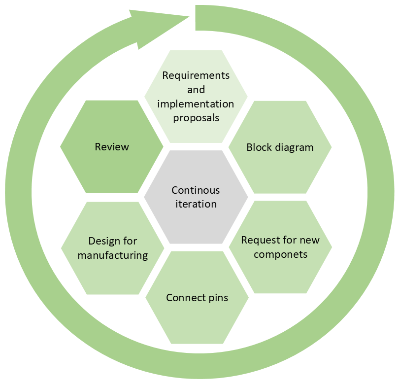
This overview describes a few of the main steps when creating a schematic however the iteration between these steps are not set and the designer will iterate between them as needed.
 |
|---|
| Overview of main steps and iterations. Note that the iterations can go between any item and even to PCB layout work. |
Detailed checklist for development work
When creating a schematic it is recommended to use the schematic design checklist. Below are some short motivations behind the checklist to support developers when using it. The checklist has been divided into different categories. Some categories are explained in more detail in the sections below:
Use checklist 7PAA010429 CD-Schematics Design Checklist (can be found in templafy).
Components
When creating circuit diagrams or schematics symbols are needed. The symbols are created by the component engineers within R&D. In order to be able to get a symbol for the component that you have chosen a request for a new component must be sent to one of the component engineers. After the request and the information have been approved then a symbol can be created.
: In the PLM system Windchill, data from the component database IHS markit is integrated inot the PLM making searches for components in IHS markit possible for all designers through windchill. The data concerning, EOL, Sourcing and Material compliance will aslo be available in the PLM.
Component choices influence several other parts of the design. It is recommended to have a close collaboration with the following teams:
- Mechanics
- FW (Firmware)
- Procurement and logistics (P&L), contact is usually handled within a project. They are responsible for the overall handling of components within PCP, negotiating prices, foreseeing issues with components, and dealing with suppliers.
- Industrial engineering (IE), are focused on the manufacturability of the product.
- PCB Layout
UL certification
The E-file number indicates that a component has been certified by UL. This certification is standard on most products. It is a good idea to use UL-certified options when possible. Typical component categories that require UL certification:
- Fuses
- Connector plastic
- Transformer
- Digital isolators
- Relay
- Optocouplers
- Housing (plastic)
- etc.
Constraints and Constraints for high speed
When defining the constraint values please consider the equations High speed design formulas. Specific component parameters need to be considered and are input to these equations.
Even at low frequencies a design needs to be considered as high speed if the rise and fall times are very fast, eg. less than 1ns(rule of thumb).
Constraint classes
These constraints are added in the constraint editor in Xpedition.
: the below items are some examples of constraints but it is not a complete list.
- General constraints (applies for all designs)
- Clearance and creepage distances
- Trace widths
- PCB stack-up, the number of layers
- Layer restrictions for signals
- High speed constraints (applies for high speed design)
- Required trace impedance
- Length matching
- Maximum stub length
Compliance to legislations and standards
From the requirements, there are requirements regarding material compliance, ATEX, safety, etc. ABB works on many different legislations and standards. Below is a short overview of some examples and how to find more information.
- Material compliance
Requirements for each product should be given through the requirements however it is important that designers try to move away from hazardous substances when possible and be aware that there are legislations impacting the work being done. ABB inside info on material compliancenote: Substances of very high concern, "SVHC" are a list of candidate substances that could be banned in future within EU. As a manufacturer you are obliged to inform downstream customers if your products contain SVHC. This is also reported to ECHA in the SCIP database.
- Explosion protection Explosion protection is important for Ex certified designs. One part of this is considering components that are classified with and E-file number. For more information on explosion protection please see Supporting process - Explosion protection
- Safety
Some products are to be added to the annex of the safety certificate this is clear from the requirements on the product. For more information please see Supporting process - Functional Safety Management
Design recommendations
These recommendations are made by hardware engineers with experience in creating schematics. These are some general considerations to have while doing design work.
- Comment items: When creating a complex circuit diagram and schematic with multiple connections and layers it is recommended to add comments to make the design more readable and understandable. These comments can also help in interpreting the design for the manufacturer when designing for instance an ICT test or a functional test.
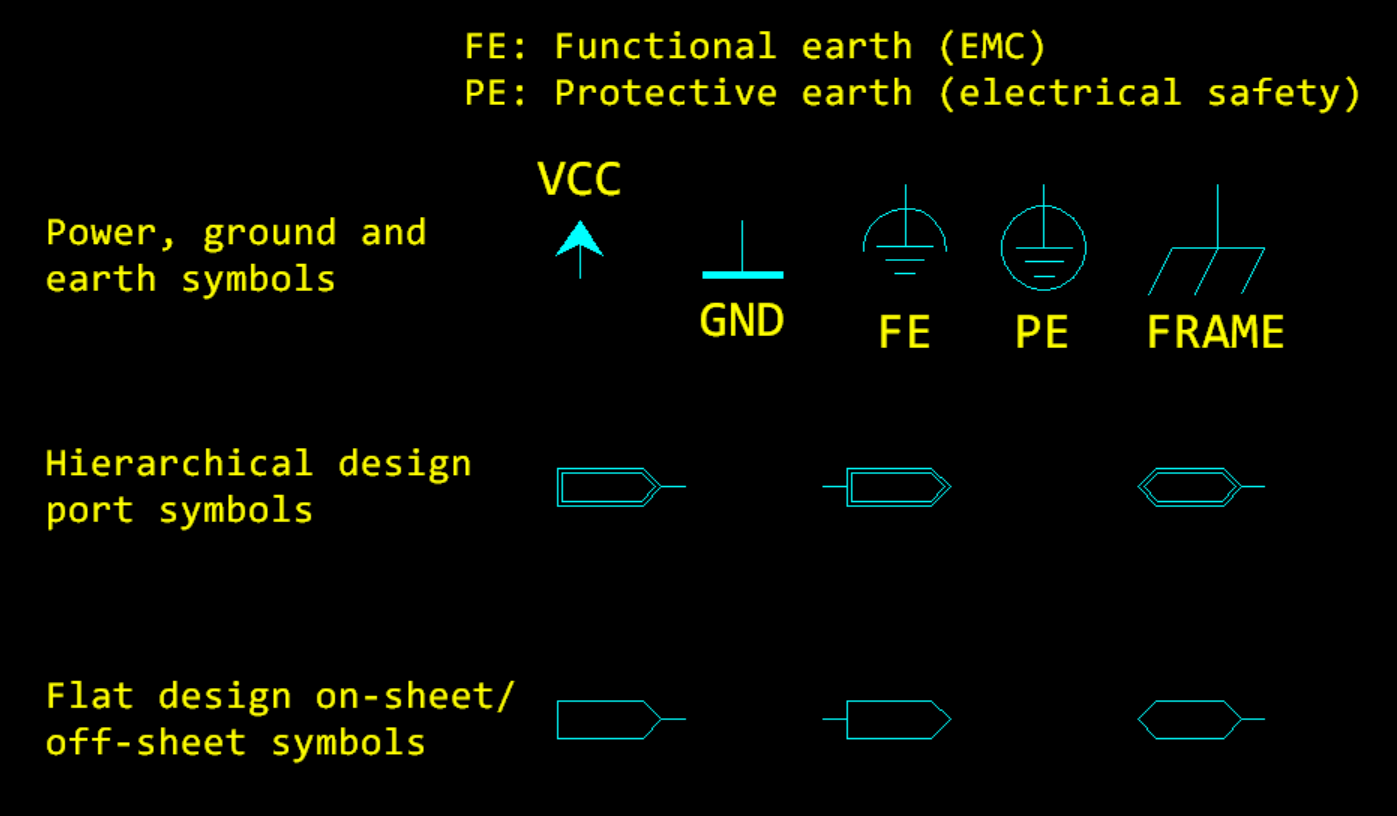
- Port symbols: These are used to indicate that the connection leaves this sheet and will help find connections on other pages. Usually, this already is in mentor.
- Hierarchical designs: With hierarchical designs, the benefits are that one can add a more complex level for every level of the design. Starting with something quite basic and then going into something very complex in steps.
- Visually indicate connections: When having several connections that are connected from point A to point B it is a benefit to have a line that indicates where the information is found on the sheet. A suggestion is to use a databus for several connections.
- Use fixed font sizes and set up projects with a config file.
- Extra documentation connections can be added into a “documentation layer” directly in mentor graphics. This is then only visible when you want it to be.
How to set up a new project in Xpedition designer
This is a tool that is used for creating the schematic or circuit diagram. In the tool, each design is called a project.
Do you need access to Xpedition designer? For each site, there is a responsible person within the hardware team that is responsible for Xpedition designer. This person requests a license for new users.
Stepwise instruction
-
Open an existing project or establish a new project. A project is a container for one or several schematics. If you create a new project, you need to set the following:
- Circuit Diagram number (For Sweden/China: In general it is the product number (communicated from the release owner) + sub-number D0002. For Germany: please contact the HW manufacturing coordination representative)
- Schematic name
-
Where to find the library. These are stored locally on servers.
- Germany: Server: \\DE-S-0228808\Mentor_Expedition IP: 10.50.10.88 (main folder with project folders and archive etc.)
- Sweden: Server: \\SE-S-0000454\ahe IP: 138.227.186.10
- China:
Server: \\CN-S-0170001.cn.abb.com\HGH1DATA$\Projects\Development projects\90 - Hardware Development\90 01 - MG Center Library\SW_lib
IP: 10.138.125.9
-
Library settings. There are different libraries used depending on where the development has historically taken place.
- Swedish library(this is also used in China): 800xA, Advant, Combitrol and Combimatic
- German library: Freelance, Melody, S900
- US library: Symphony and S+
-
Set boarders and zones. If assistance is required ask local administrators for Xpedition designer for advice.
- Drawing size. Depending on what library will be used this shall always be A3 if the Swedish library. For the German library sheet size shall be A2.
To create this. Right click on the blank space of the boarders. Press “Properties”. Press “Drawing Size” and choose A3.
note: Symbols for IC in the schematic should be used in an upright position whenever possible. This could be facilitated by using A2 sheet size. Large symbols require A2. Note: The Swedish symbols library is based on the metric system. The German symbols library is based on the Imperial system that uses inches.
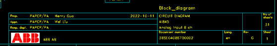
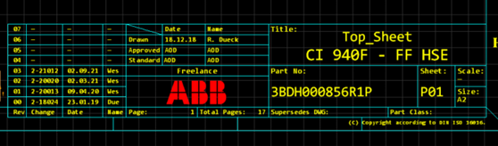
Schematics boarder appearance for designs made in Hangzhou and Sweden Schematics boarder appearence for designs made in Germany - Drawing size. Depending on what library will be used this shall always be A3 if the Swedish library. For the German library sheet size shall be A2.
-
Boarders. Boarders are different depending on what library is being used. It is also different based on if it is a A2 or A3 sheet size.
-
Go to setup. Press “Settings”. Press “Boarders and Zones”. Press Boarder symbol for first sheet/boarder symbol for next sheet. Standard boarders to use:
- ABB_a2sheet_name.1 (Swedish library, A2)
- ABB_a3sheet_name10.1 (Swedish library, A3)
- a2sheet_abb_vx.1 (German library, A2)
- a3sheet_abb_vx.1 (German library, A3)
-
Boarder properties, include:
- Go to setup. Press “Settings”. Press “Boarders and Zones”. Press “Boarder properties”
- Date
- Document number
- Revision
- Design description
- Author
- Preparing department
- Responsible department
- Sheet number. Sheet numbers are updated under “tools”. Press update “Other objects”. Press “Print Order”. Press “OK”
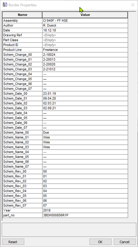
Boarder properties settings view - Go to setup. Press “Settings”. Press “Boarders and Zones”. Press “Boarder properties”
-
-
Font. Press setup. Press settings. Press display. Press font styles. Press the style “Fixed” and choose the font Arial for the Swedish library, with the German library Consolas should be used. A suggestion is to use a monospace font style such as Consolas as it makes creating tables easier.
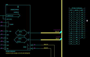
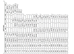
Table with monospace font Table without monospace font - Font: Monospace font, Consolas.
- Font Size: according to table.
-
Line settings
- Line width
- Bus: 10
- Others: 1
- Color: Automatic Press “Setup”. Press “Settings”. Press “Display”. Press “Objects”. Press “net”. Press “1”
- Line width
-
Setting the Navigator tree view (Xpedition project structure) Press setup. Press settings. Press Navigator. Press symbols: Lablel format: (Name)
note: having the internal names of the symbols is useful in case of warning or error messages as these often refer to the internal ID = $(Name)
-
Special components settings
-
Input and output connectors, powers, and grounds. These symbols should have the following appearance.

Sweden and China Germany
-
-
Component selection
- Swedish library: Always try to use the list of preferred components in the symbols library. Please request for a new component (from the component engineers) if you need something that is not already present in the symbols library.
note: There are ongoing dicsussions regarding preferred components, please consult your component engineer for the latest information.
- German library: Only has the current components. Which means that all components are preferred components. Please consider the lifecycle status in EOL(End of life) property and NRND (not recommended for new designs).
-
Component labeling
Should include reference designator, value, part name, pin number, asterisk for Not mounted components, and Ex for explosion proof components.- If component is relevant for Ex then add the function label "Ex".
- Indicate not mounted components:
- Germany: use the Variant manager from xpedition
- Sweden and China: Add the property "donotmount" as property value "*"
-
Reference designator settings shall follow the following format, example below.
A1701 :
- A = Analog Chip
- 17 = Page of the schematic
- 01 = Serial number
R C V T A D L X B Resistance Capacitance Diode/triode Transformer Analog Chip Digital Chip Inductance Connectors Crystals -
Sticker symbol For Safety, Ex design and for all designs that are certified by UL. A sticker needs to be places stating that the drawing must not be changed without written permission from respresentatives.