How-to Create a New Mechanics Design
Mechanics includes all parts that are not electrical, such as housings, baseplates, and labels. All mechanics are created in a CAD tool.
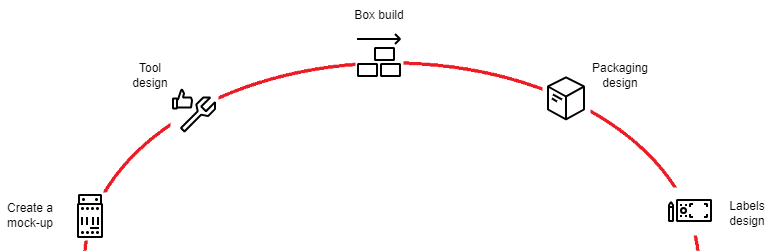
The mechanical design of a product involves more than the physical design of the product. It also includes the development and design of a mock-up, manufacturing tool, box build, packaging, and labels.
Intended for
Hardware engineers (mechanics).
Activities
Create a mock-up
A mock-up can be any of the following and can represent the whole design or a part of the design:
- 3D drawing of the design.
- 3D printed prototype.
- A sample of any kind.
-
Create drawings. Drawings are made for design items that are developed by the mechanical team. At the very beginning of new development, the designer creates a 3D design of the product. This can contain one or several articles that make up the final product.
-
Validate the design. This can be done in various ways:
- Simulate the design using an applicable tool for analysis.
- Create a 3D printout.
- Etc.
-
Peer-review the design. Review the design within the team and exchange experiences. Also, validate this early design with electronic design.
-
Request for new component. This gives the design a customer part number (CPN).
-
Send the design to the industrial designer (this step is only done once per product family). The industrial designer (external party often) is responsible for stating the look and feel of the product. This results in a design guide that is reviewed and approved (between the mechanics team, product owner, and industrial designer) and stored in the product lifecycle management tool Windchill PLM.
Output:
- Design guideline: general for product family.
- 3D design of product.
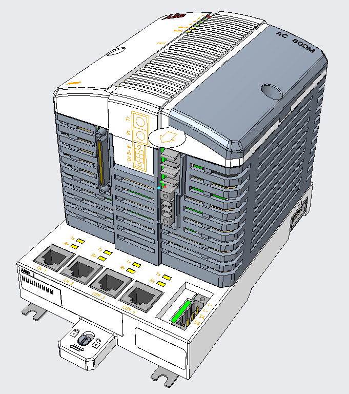 |
|---|
| Example of a 3D design. |
Tool design
The creation of the tool is a collaboration between Industrial Engineering and R&D mainly. Industrial Engineering owns the tool and makes the necessary checks on the maintenance of the tool and ABB ID. They also have a responsibility to check the manufacturability. This means that R&D is responsible for the design but is also obliged to involve industrial engineers in the design as well as in the tool purchase.
-
Align with Procurement & Logistics (P&L) about the choice of the supplier.
Note: This item is usually handled within a project and by the release owners. If the designer wishes to use a new supplier, note that this supplier must be approved by P&L before any purchase can be made (4-8 weeks lead time before purchase).
-
Send requirements to the manufacturer selected. Also, send the mock-up design and the specifications on the materials to be used (from the design guideline) to the supplier.
- Mock-up drawing
- Requirements and tolerances on the product that comes out of the tool.
-
Ask for a quote for the tool.
-
Quote review between R&D and Industrial Engineering.
-
Create a purchase order for the tool based on the quote, see Who pays for the tools?
-
Receive samples from the tool.
Iterate several samples from the tool until the tool tolerances are acceptable and the Sample approval checklist is done.
Output:
-
Approved product associated with the tool.
Note: If the product is updated consideration must be taken if the tool needs to be updated in the process. In the smallest case, there will only be a new delivery of a drawing to the manufacturer. In a larger change, it might mean a new tool. Involve Industrial Engineering when tool discussions are ongoing.
Who pays for the tools?
The release owner is responsible for aligning this between the different operations. Independent of who purchases the tool the maintenance of the tool is under Industrial Engineering responsibility. There are two main options:
-
The tool is within Industrial Engineering's budget. Industrial engineering creates a budget in September for the coming year. If a new tool purchase is planned within this budget, then Industrial Engineering can pay for it.
-
The tool is not within Industrial Engineering's budget. If Industrial Engineering is requested to release the purchase order and then take the cost of the tool, then Industrial Engineering has the right to say no. Discussion will arise. An option can be that R&D pays for the tool and handles the purchase order.
Box build
It is recommended to do the box build in parallel with the tool design. The box build activity is performed at the site where the assembly is supposed to take place.
- Box build drawing (assembly drawing).
Create a box build drawing of how the product is intended to be assembled. - Peer review.
Review and approve the box build within the team - Send to electronic manufacturing services (EMS).
The box build drawing is sent to the EMS which then tests the steps of the assembly in their production. If there are any changes needed to the assembly or the design the EMS is to report back to the mechanics team. - Verification of box build is done in product approval.
Output: approved box build data.
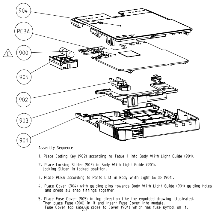 |
|---|
| Example of a box build instruction, assembly drawing. |
Packaging design
- Send design to package supplier.
This supplier then creates a package that suits the product. Deliver the following to the package manufacturer:- Drawing of product
- Include if any accessories (cables etc.) are needed to be in the package.
- Include branding information.
- Ask for a quote for the tool.
- Create a purchase order for the tool based on the quote. This is done by the release owner.
- Approve sample.
Review and approve the package sample. Consider using the sample approval checklist.
Output: approved packaging
Labels design
Labels - also called markings - are present both on the product and on the package itself. This step is typically done when the tool is being manufactured.
-
Create drawings that describe the following aspects of the markings:
- Location (where on the product)
- Specification (label type, size, etc.)
- Content (what shall be stated)
- Also, include branding information. The artifacts "marking data" and "marking placement" come out of this.
Note: Updates on labels are typically made when there are changes to any of the following fields:
- Product revision.
- Certifications.
- Etc.
-
Review. A review of these documents is done (marking data and marking placement are always reviewed together).
-
Final verification is done in product approval.
Output: labels with correct markings.
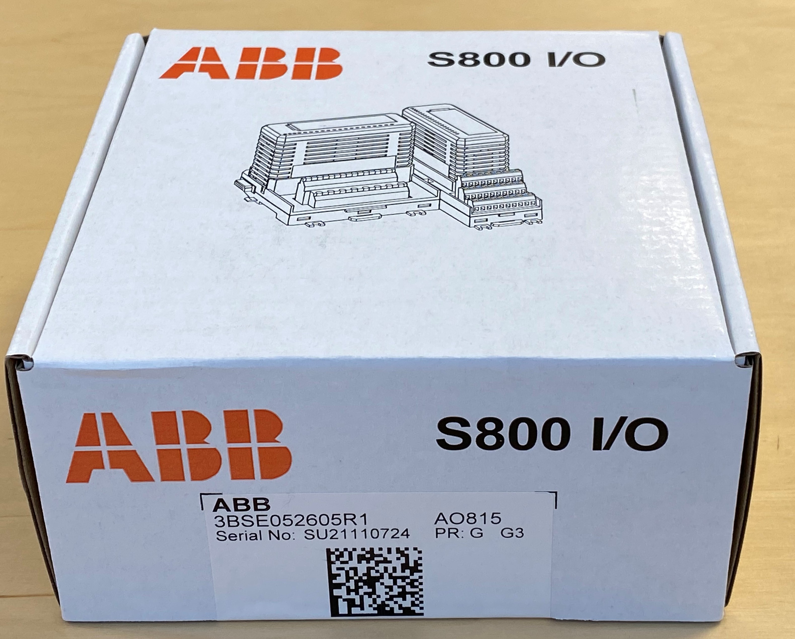 |
|---|
| Example of package. |
Details
Branding
Both the labels and the packaging shall also follow the ABB branding guidelines.
- Process automation guidelines on Branding.
Note: You need to be signed in to ABB Media Bank to access the file – top right corner.
- Product branding.
- Packaging.
Artifacts summary
| Mechanics related artifacts | Description | Where used |
|---|---|---|
| Assembly drawing | Assembly instruction and position of components and parts of the total product. | EMS |
| Component specifications | Mechanical specification including tolerances etc. | Manufacturer of part |
| Label information content | What needs to be on the label, drawing indicating exact text, letter size, data matrix code (DMC) format, whatever else, when it comes to what to be marked "Created in CAD software". This is currently not created in a specific document and which document depends on the product line. Consult the mechanics team for more information. | Manufacturer |
| Label information location | Where on the product/package the label "Created in CAD software" will sit. This is currently not created in a specific document and which document depends on the product line. Consult the mechanics team for more information. | Manufacturer |
| Label information specification | Specification of label type, material, and size for "Created in CAD software" label. This is currently not created in a specific document and which document depends on the product line. Consult the mechanics team for more information. | Manufacturer |
| Packing requirements | This is a CAD model of the product which we send to a packing company as a base of the design of the product package. | Manufacturer |
| Design guide | Document created by industrial designer that describes the look and feel of the product | Within R&D |
| Design description (DD) PCB mechanical, also known as "Obstruct drawing" | 3D drawing that describes where the product mechanical parts are. This is then used in the PCB Layout process. | In layout work |
References
About branding:
- Process automation guidelines on Branding
Note: You need to be signed in to ABB Media Bank to access the file – top right corner.
- Product branding
- Packaging
Other related items: