7 Safety Handbook - Artifacts
The purpose of this document is to provide an overview of the safety-related artifacts that need to be created during the development of a safety product in addition to the artifacts required for related non-safety development.
Functional Safety Add-On
The following figure shows the development workflow according to the 'V-Model'. The activities and artifacts related to the development of functional safety are marked in yellow:
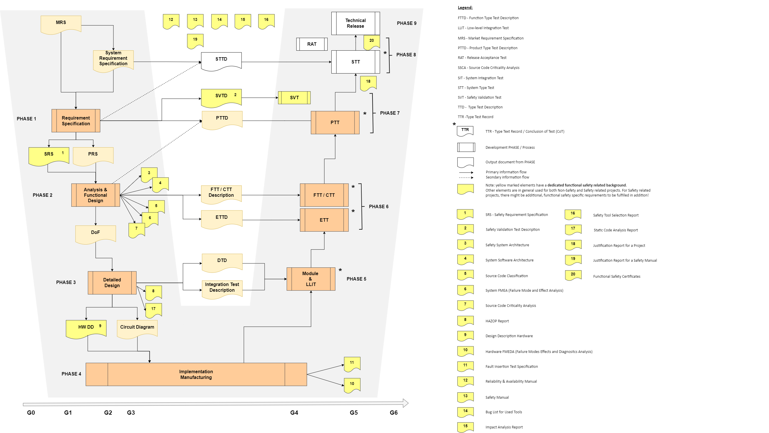
To the yellow marked artifacts as listed in the figure by number, there is for each a generic description and some explanations as brief responses to the following questions:
- Why do we need it?
- Who must prepare/create it?
- When do we need to create it (ready date)?
- How to create it (what tools to be used)?
- What is the input for it? (information needed)
- What is the output of it? (what artifact, for whom)
- Where to find the relevant detailed information? (where to find the link(s))
1. Safety Requirement Specification
The objective of the Safety Requirement Specification is to describe the main properties of the safety systems being developed and to specify the requirements necessary to make a system with a sufficient level of safety and availability. The document focuses on requirements for diagnostics, supervision, fault reaction and architecture.
| 1 | Safety Requirement Specification → Activity: Specification of Safety Requirements |
|---|---|
| Why | Complete and detailed definition of the Safety related requirements according to IEC61508 |
| who | Same group as responsible for PRS plus SE |
| when | PHASE 1, prior to Gate 2 to have the requirements clearly defined before starting development |
| how | Using the same tools as for product requirements. |
| input | Market Requirements Specification (customer use case requirements plus requirements industry standards) |
| output | Approved Safety Requirement Specification |
| where | further information to be found under: 3BSE033610 Requirements Development and Management Process 3BSE080908 Working with requirements in TFS 3BSE073542 Working with requirements in Safety case DB |
2. Safety Validation Test Description
The Safety Validation Test Description (SVTD) documents the tests that are needed to verify all specified and approved safety requirements.
| 2 | SVTD → Activity: description of the safety validation test |
|---|---|
| Why | It is required to validate the system against the Safety Requirement Specification/PRS. |
| who | Test team; involving SE |
| when | After Gate 3, prior to Gate 4; Needed as input for the SVT execution between G4 and G5 |
| how | Template for test instruction to be used to enter all relevant test cases; Each safety requirement needs a test case for validation. |
| input | Safety Requirement Specification and DoF |
| output | Approved SVTD; This is then input to the SVT ending in an SVT Record. |
| where | further information to be found under [A40] Safety Validation Test Process [A55] AutoSVT Code Review Guideline |
3. Safety System Architecture
The Safety System Architecture describes the overall system architecture of the safety systems. It briefly describes the main system components and gives an overview of the safety functions implemented in the different subsystems.
| 3 | Safety System Architecture → Activity: creating safety system architecture |
|---|---|
| Why | A Safety System Architecture is essential for the understanding of the overall Safety functionality. Basis for the design and basis for changes to be done later when the product has entered the maintenance life cycle phase. |
| who | R&D, SE |
| when | At the beginning of a Safety development, immediately after G2, ready at G3. |
| how | Documenting the architecture (e.g. in an MS Word document) |
| input | Requirements, (initial) concepts, knowledge about all system parts |
| output | Approved Safety System Architecture |
| where | further information contact the 'Functional Safety Team'. |
4. System SW Architecture
The System Software Architecture describes the entire software architecture (i.e., not only Safety parts) in static views, describing how the system is structured, and runtime behavior views with interaction between elements in the system. References to Descriptions of Function, Descriptions of Design and other relevant documentation, as well as mapping to the source code, are also part of this document.
| 4 | System SW Architecture → Activity: creating system software architecture |
|---|---|
| Why | Essential for the understanding of the overall (complex) SW functionality. Not a specific Safety document but in general needed for complex SW. Basis for the design. |
| who | SW architect, SW developers; for safety related SW, the SE needs to be involved in the review process. |
| when | At the beginning of a SW development, immediately after G2, ready at G3. |
| how | Documenting the architecture in a document (e.g. in a MS Word document); using UML based tools (like Enterprise Architect) |
| input | Output from analysis and functional design (DoF) and other existing system architecture documents. |
| output | Approved System Software Architecture |
| where | Contact the SW development responsible process team |
5. Source Code Classification / Code Criticality Classification
States the resulting Safety Integrity Level (SIL) for each source code module/component/file. The information in this document is closely related to the information in the System and Software Criticality Analysis document, but directly connected to the source code structure, and presented on a detailed level, to be used as input for the software developers. The document shall be able to answer what SIL a specific code part has. This information is essential when concluding what development rules apply to that code part.
| 5 | Source Code Classification / Code Criticality Classification → Activity: Classification of the Source Code |
|---|---|
| Why | To aid the SW developers in their detailed design work. To be able to answer on a detailed level what SIL the code parts have. States the resulting Safety Integrity Level (SIL) for each source code module/component/file. |
| who | SW developer; involving SE in review |
| when | PHASE 2: Analysis and functional Design |
| how | Documenting the Source Code Classification (e.g. in an MS Excel document) |
| input | Output from analysis and functional design (DoF) |
| output | Approved System Software Architecture |
| where | For further information contact the SW development responsible process team. |
6. System Failure Modes and Effects Analysis
This document describes the results of the system FMEA. A Failure Modes and Effects Analysis (FMEA) is a systematic way to identify and evaluate the effects of different component failure modes, to determine what could eliminate or reduce the chance of failure, and to document the system in consideration.
| 6 | System FMEA → Activity: analyzing and documenting the failure modes and its effects of the safety function |
|---|---|
| Why | A Failure Modes and Effects Analysis is a systematic way to reduce the chance of a systematic failure, and to document the system in consideration. |
| who | R&D, SE |
| when | Can be started at the beginning of a Safety development on basic concepts (e.g. power supply, interfaces, …). To be completed prior to G2. |
| how | Systematic identification and evaluation of the effects of different component failure modes (e.g. in an MS Word document). |
| input | Output from analysis and functional design (DoF) |
| output | Approved System FMEA |
| where | For further information contact the Functional Safety responsible process team. |
7. System SW Criticality Analysis
The System and Software Criticality analysis provides the argumentation for the selected Verification & Validation activities applied to the different SW parts. The architecture and detailed design of the system or software sub-system are structured into units of different Safety Criticality. The criticality allocation shall be limited to system or software units, which have clearly restricted functionality and interface. Units of lower Safety Criticality shall not interfere with units of higher Safety Criticality. System FMEA, HAZOP and Fault Trees are recommended methods to perform the analysis and allocation of System / Software Criticality. Based on the results of the Criticality Analysis and allocation, the required compliance for development, V&V and modification of the individual system or software is given. As an example, a system with pre-existing code may identify functions that need to be re-engineered, supervised by safety measures and/or especially tested.
| 7 | System SW Criticality Analysis → Activity: Analysis of the criticality of the system SW and its functions |
|---|---|
| Why | The criticality analysis is done to provide argumentation for reducing the SIL when developing SW sub-modules after modularization of the SW. The results are providing the argumentation for the needed measures in design and Verification & Validation activities applied to the different SW parts. |
| who | R&D, SE |
| when | At the beginning of a Safety SW development, using input from architecture document(s) |
| how | FMEA, HAZOP and Fault Trees Analysis are recommended methods to perform the analysis and allocation of System / Software Criticality. The architecture and detailed design of the system or software sub-system is structured into units of different Safety Criticality. The criticality allocation shall be limited to system or software units, which have clearly restricted functionality and interface. Units of lower Safety Criticality shall not interfere with units of higher Safety Criticality. |
| input | Output from architecture, analysis and functional design (DoF) |
| output | Based on the results of the Criticality Analysis and allocation, the required compliance for development, V&V and modification of the individual system or software, is given. |
| where | further information to be found under the Safety Handbook subsection Criticality |
8. Hazard and Operability Analysis
A Pre-Hazard and OPerability analysis is a formally structured analysis using HAZOP methodology. The pre-HAZOP can be performed at an early stage of the project (prior to Gate 2). The purpose of a pre-HAZOP is to find potential problems already considering raw input, e.g. block diagrams.
The purpose of a Hazard and Operability analysis report is to document the details and the results of the HAZOP carried out. It is meant to be the evidence document for the correctness of the SIL reductions done during the development and an input document for the final Safety Criticality Document, showing in detail which safety measures are relevant for which SW component.
The purpose of a HAZOP analysis is to identify what potentially hazardous variations from the design intent could occur within components or in the interactions between components of a system. Those deviations can be caused by systematic software failures or random hardware failures. Not applicable for Libraries since HAZOPs are not valid for Libraries. A HAZOP shall be performed for new functionality or error corrections. If not performed, a rationale shall be given in the 'quality log'.
| 8 | HAZOP |
|---|---|
| Why | - Pre-HAZOP: to find potential problems already considering raw input; - HAZOP: Identification of what potentially hazardous variations from the design intent could occur within components or in the interactions between components of a system; Those deviations can be caused by systematic software failures or random hardware failures. Providing the evidence for the correctness of the SIL reductions done during the development. " |
| who | A group consisting of a limited number of subject matter experts (e.g. HW, SW, SE) bringing in different viewpoints. |
| when | - Pre-HAZOP: at an early stage, prior to Gate 2; - HAZOP: based on the design, after Gate 3" |
| how | Using a HAZOP tool (e.g. Exida SILCAP, SafetyInsight, ...) |
| input | - Pre-HAZOP: The input documents for the Pre-HAZOP could be the Product Requirement Specification (PRS), the Safety Requirement Specification (SafetyRS), the Implementation Proposal (IP), the System Software Architecture, the Safety System Architecture or other types of early project descriptions. Raw input possible, like e.g. block diagrams; - HAZOP: The input documents for the HAZOP could be the Description of Functions (DoF) and/or the Design Description (DD) and the Safety Criticality Document." |
| output | HAZOP report; input document for the final Safety Criticality Document, showing in detail which safety measures are relevant for which SW component. |
| where | further information to be found under Guideline for HAZOP |
9. Design Description Hardware
A Design Description Hardware describes in plain text the reasoning for some parts of the hardware diagrams (= schematics) in addition to the drawings (= schematics).
| 9 | DD HW |
|---|---|
| Why | Providing additional information to explain the chosen design of the HW schematics for a better understanding in later years (new R&D staff, modifications, …) |
| who | HW developer |
| when | During HW design |
| how | Description of any special functions or choices made for the design of the HW circuitry |
| input | HW schematics and DoF |
| output | Approved DD HW |
| where | further information to be found under Hardware Development Process |
10. PFD/PFH calculation and HW FMEDA
This R&D internal document contains information necessary to support dependability studies and availability and reliability calculations for the safety system. It includes methods and data to be used in the calculations of system reliability both from availability as well as from a safety reliability viewpoint. The resulting PFD/PFH values are documented in the corresponding user manual, see Reliability and Availability Manual, ref [A36].
| 10 | HW Failure Mode Effects and Diagnostics Analysis |
|---|---|
| Why | required by the IEC 61508-2-7.4.5 to quantify random failures (HW safety integrity); needed as input for reliability manual and as input for final SIL classification/justification |
| who | HW developer, SE |
| when | PHASE 3: After HW schematics are ready, after G3 |
| how | Going through the HW schematics by evaluating part by part; entering the results in an adequate tool; currently used tool: Exida SILCAL |
| input | HW schematics (incl. BoM) + information about diagnostics |
| output | Tool report including PFD/PFH values for single modules |
| where | For further information address to the Safety Team |
11. Fault Insertion Test Specification
This document provides the required fault insertion tests to verify the correctness of the assumptions of the system which is stated in the system FMEA and the component FMEDAs.
| 11 | FIT Specification |
|---|---|
| Why | To verify the correctness of the assumptions of the system which is stated in the system FMEA and the FMEDAs. |
| who | R&D (HW and SW) |
| when | PHASE 4, after the detailed design has been accomplished. |
| how | Evaluation of the assumption on the system and elaboration of methods that allow to assess the proper safety functions of the system under test. |
| input | Architecture, DoF and detailed design |
| output | Approve Fault Insertion Test Specification including the definition of the test setup |
| where | For selection of FIT test cases, see ref [A5]. |
12. Reliability & Availability Manual
Describe under what conditions the PFD and PFH values are met for the Safety System. The Reliability Manual also gives the numbers that can be used for calculating the PFD/PFH for an individual configuration.
| 12 | Reliability & Availability Manual |
|---|---|
| Why | Document required for end user as input for Safety loop / calculation of Safety Integrated Function. |
| who | Safety Engineer or Technical Writer; Review by SE required (different than author); SE is in responsibility for the reliability content. |
| when | Prior to Gate 5; work can be started after the design is in place. |
| how | Writing the content to the adequate template; tool to be used: Skribenta |
| input | FMEDA: reliability figures; further calculated where needed (e.g. in case of redundancy) |
| output | User manual: "Reliability & Availability Manual" |
| where | For further information address to the Safety Team |
13. Safety Manual
Describes the Life Cycle Requirements for the safe operations of the Safety System. Performance data stated in the Safety Manual are validated by related SVT.
| 13 | Safety Manual |
|---|---|
| Why | Document required for end user as input for safety commissioning and operation of the SIS. |
| who | Safety Engineer or Technical Writer; Review by SE required (different than author) |
| when | Prior to Gate 5; work can be started after the design is in place. |
| how | Writing the content to the adequate template; tool to be used: Skribenta |
| input | DoF; user manuals; possibly results of the HAZOP |
| output | User manual: "Safety Manual" |
| where | For further information address to the Safety Team |
14. Bug List Used tools
To ensure that the safety product complies with the safety requirements applicable at the level chosen, the bugs in used products, e.g., OS, must be considered. For each bug, it is judged if it affects safety functionality or not and what actions are taken.
| 14 | Bug List Used tools |
|---|---|
| Why | Avoiding mistakes when using tools |
| who | R&D; Configuration Management; teams maintaining and using the tools |
| when | from the introduction of the tool until its decomissioning |
| how | Form doesn't matter - completeness is important |
| input | List of known bugs and workarounds from vendor plus further bugs and workarounds if not on already available on the list from tool vendor |
| output | List of known bugs and workarounds for the respective tool |
| where | Contact the tool responsible person (List of tool responsible persons is in DFN) |
15. Impact Analysis Report
The Impact Analysis Report is a document describing all modifications (new development as well as error corrections) made to the certified system since the last certification, including impact on the system, description of the changes, necessary retest etc. This report is required for each release of an already certified system/product (system version, rollup etc.).
The Impact Analysis is created by answering the relevant, predefined questions in the analysis tab in the corresponding work item.
The Impact Analysis Report is then typically created by tool-supported parsing of the contents in the “analysis” tabs of the relevant ADO work items and providing them as an overview in a separate document.
| 15 | IA Report -> Activity: performing IA and creating a report |
|---|---|
| Why | The Impact Analysis is done when modifying a safety system to assess the impact of the modification on functional safety and to identify which lifecycle activities need to be repeated. Impact Analysis Report combines the IA results in one document that needs to be handed over to TÜV, preferably as a report for assessment as input for certification. |
| who | Project Manager; SE to be involved in review |
| when | After the impact analysis of the safety related work items have been approved; prior to the certification = prior to the release of a product or function. |
| how | Creation of the report from the tool where the IA is done (e.g. Azure DevOps). Typically done by means of a tool (e.g. Scribe tool). |
| input | Impact Analysis of all work items (e.g. bug and features), that are relevant for Functional Safety. |
| output | Approved Impact Analysis Report as a MS Word document |
| where | further information to be found under [A28] or contact the process team responsible for Functional Safety. How to fill in an impact analysis is an activity related to the work item it relates to. |
16. Safety Tool Selection Report
This justification document contains the argumentation of why the selected tool is suitable for use in the safety development environment.
| 16 | Safety Tool Selection Report -> Activity: Assessment of a new tool or new version of a tool with respect to functional safety |
|---|---|
| Why | Each and every tool used in the Safety development needs a justification as required by the standard IEC 61508-3 7.4.4 |
| who | The responsible person requesting to introduce the tool; SE needs to be involved in the review |
| when | In the context of or respectively prior to introducing a new tool or new version of a tool |
| how | Filling in the Safety Tool Selection Report based on the existing template. And perform a review on that document. |
| input | Information about the tool: the manual, its purpose, information how it works, ... |
| output | Approved Safety Tool Selection Report for the selected tool |
| where | The template is available in templafy (ID 7PAA004621F); Guidance on how to fill in is available as 'hidden help text' in the template. |
17. Static Code Analysis Report
Handles the outcome of Static Code Analysis. The document lists the tools used and presents evidence for the static code analysis accomplishment.
| 17 | Static Code Analysis |
|---|---|
| Why | Static code analysis, or static analysis, is a software verification activity that analyzes source code for quality, reliability, and security without executing the code. Using static analysis, you can identify defects and security vulnerabilities that can compromise the safety and security of your application. Analysis of source code for improving quality, reliability, and security, by identifying defects and security vulnerabilities that could compromise the safety and security of a SW function. |
| who | SW R&D |
| when | During development / SW build |
| how | Automatically executed via tools (e.g PC-Lint, Parasoft, ...) in on the build machine. |
| input | Source code |
| output | Static Code Analysis Report on the the code under test. |
| where | "For SW: < [A17] “Static Code Analysis Guideline”> |
18. Justification Report for a project (and burner library)
The justification report documents all requirements and the coverage of each of those requirements with respect to its solution and the corresponding test case.
| 18 | Justification Report for a project (and burner library) |
|---|---|
| Why | Ensuring / proving completeness by indicating: - Traceability between Requirement ↔ Solution - Traceability between Requirement ↔Test |
| who | Project Manager |
| when | Prior to the final conclusion of test in order ensure test completeness |
| how | Providing an overview (e.g. via an MS Excel spread sheet) |
| input | Requirement Specification, DoF and Test Description |
| output | Justification Report for a specific development project |
| where | ABB Approach to Traceability ref [A37] |
19. Justification Report for a Safety Manual
All claims provided in the safety manual for compliant items need a documented justification (see ref [B3], [B4]). The Safety Manual Justification Report provides for each claim the reference to the evidence/test providing the claim to be fulfilled. The Safety Manual Justification Report does not need to be generally disclosed, i.e., not published to the user. For supporting interpretation of the normative requirements and how to implement them in the Safety Manual Justification Report see [A7], [A37].
| 19 | Justification Report for a Safety Manual |
|---|---|
| Why | According to IEC 61508, each claim that has been made in a Safety Manual has to be justified. |
| who | Author of the Safety Manual |
| when | During the writing of the Safety Manual, latest at approval of the Safety Manual |
| how | Done via a hidden (= unpublished) table as a part of the Safety Manual in an additional chapter at the end. |
| input | Safety Manual |
| output | Safety Manual Justification Report consisting of the Safety Manual including a section providing evidence for each claim. |
| where | For further information address to the Safety Team |
20. Functional Safety Certificates
The functional safety-related certificates comprise those documents issued by the certification body as proof of compliance with the relevant safety standards and as a precondition for placing the products into the markets.
| 20 | Functional Safety Certificates → Activity: Certification by Certification Body |
|---|---|
| Why | Granted certificates are a precondition for product release. Certificates include the Safety Certificate including the Annex, both based on reports |
| who | Certification Body - TÜV-Süd |
| when | At Gate 5 (precondition to pass G5) |
| how | Providing all certification relevant documents to the certification body and answering all questions in the context of the certification. |
| input | All documents required by the standard and requested by the certification body |
| output | Certificate with reports (with the certificate to be published to the customer) |
| where | Further information to be found under: Functional Safety Process 7PAA006341_en List of active Safety Certificates How-to Manage Functional Safety certification documents |
Safety Operator Warnings Manual
Combines the warnings of all the user manuals for one product in one document. Especially after translation into national languages, this complete set of warnings supports the plant operator.