Safety Handbook
The purpose of this handbook is to describe how to perform quality assurance during a safety project in addition to the Quality Management System. Other documents with "Safety Handbook" in the title belong to this Safety Handbook. Although existing as separate documents they are functionally integrated parts and as such are linked in the Safety Handbook. Those documents are:
- Safety Handbook - NonSIL: Recommended SIL1
- Safety Handbook - NonSIL - Library
- Safety Handbook - SIL1
- Safety Handbook - SIL2
- Safety Handbook - SIL3
- Safety Handbook - SIL-Library
- Safety Handbook - Artifacts
- Safety Handbook - Reference List
General
Introduction
This handbook shall be used together with the Quality Plan template ref [A15], which shall then contain the functional safety-related specifics.
The main purpose of this Safety Handbook together with the Quality Plan for the project is to fulfill the standard IEC 61508 [B1] for Safety products and IEC 61511 [B9] for Libraries. This Safety Handbook can be used for non-safety products on an optional basis. All projects developing interference-free parts shall adhere to this document.
For other information on how to handle functional safety-related specifics (e.g. training, certification, ...) see the Functional Safety webpage.
Description of the Safety Life Cycle
According to the IEC 61508 (ref [B5] and ref [B2]), the safety life cycle comprehends: "Necessary activities involved in the implementation of safety-related systems, occurring during a period of time that starts at the concept phase of a product and finishes when all of the E/E/PE safety-related systems, other technology safety-related systems and external risk reduction facilities are no longer available for use."
This Safety Handbook covers the whole Safety Life Cycle of the product until and after product release. This Safety Life Cycle is defined by 10 PHASES, see Definition of development PHASES.
The development of a new product shall follow the whole V-model as described in this Safety Handbook. This means that all life cycle phases shall be followed.
The Product Maintenance Process is responsible for the Safety Life Cycle after product release. Potential modifications of a product after release shall be evaluated regarding their scope and impact following the rules of the Configuration Management. Depending on scope and impact, the modification process might then be reduced to a subset of the PHASES in the V-Model. Such a tailoring (= reduction of the scope) needs to be documented in the Quality Plan.
Security
Security issues can have an impact on functional safety. To minimize this potential impact on safety products, the Security Handbook [A56] shall be observed during the overall life cycle of safety products.
Linking and purpose of key safety-related documents
The following figure shows the connection between key safety-related documents:
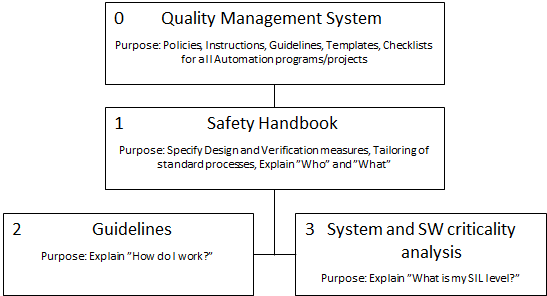
[0] Quality Management System defines the work methods and general workflow for product development projects. This is valid for all kinds of development (Non-Safety and Safety related)
[1] Safety Handbook defines the work methods and general workflow for safety product development projects. This is an 'add-on' to the 'Quality Management System', valid for Safety development.
[2] Guidelines supply guidance and assistance on "how" these techniques and measures shall be performed.
[3] System and SW criticality analysis defines the applicable Safety Integrity Level for sub-functions, the overall function has been split into.
See Roles for a description of roles and responsibilities involved in development projects.
Planning
Quality & Safety Planning
The following figure shows the hierarchy of the 'Quality Plan':
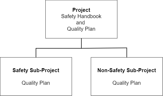
Safety Projects
Projects that develop safety functions need to create a Quality Plan [A15] with safety-related chapters. ABB PCP R&D does not have a specific Safety Plan but the contents of that artifact is integrated in the Quality Plan.
Safety Sub-Projects
Safety-related sub-projects need to follow the Quality Plan of the superior Safety Project or can create a Quality Plan of their own with safety-related chapters. The decision on which way to go is up to the project.
Non-Safety Sub-Projects
Non-safety-related sub-projects should create a Quality Plan based on the Quality Plan template [A15] and write 'N/A' on safety chapters.
Deciding about the functional safety development to follow
Kinds of functional safety-related development
- Non-Safety – The product is not capable of operating in safety functions and does not operate with safety products.
- Non SIL: Recommended SIL 1 – The product is not certified but the development is following rules for safety development.
- Interference-free – The product is not safety-certified but could be operated together with safety-certified products. The interference freeness needs to be proven, for the initial development and in the context of modifications.
- Safety-relevant – Components used for building up the safety system with no added functionality or impact on the safety system. They are typically HW components attached to the safety system such as field termination units and parts of a black channel.
- SIL 1…3 – The product is capable of operating in safety functions up to the certified SIL.
Deciding the safety level
The initial decision about the safety level of the product or the function to be developed is defined in the requirement specification. This definition shall be ready prior to approval of the Market Requirement Specification (MRS) (prior to Gate 1):
- If the product shall be safety-certified, then the SIL needs to be defined prior to the approval of the safety requirements specification (prior to Gate 2).
- For complex SW functionality consisting of various modular SW functions the "System and Software Criticality Analysis" can be used to define the applicable SIL of the modular SW functions.
- If the product shall not be safety-certified but operates together with safety-certified products or functions, then this product shall not interfere with the safety functionality. The product/component under development is then handled as "interference-free" and its development needs to follow the rules for interference freeness. (decision about prior to Gate 2)
- It is possible that a product shall not be safety certified, but the development shall follow the rules for safety development (e.g. SIL1). This is a management decision and the safety rules have then to be followed based on this decision. (decision about prior to Gate 2)
After the Safety level has been defined by the approval of the MRS, the required safety-related setup for the project needs to be defined in the safety section(s) of the Quality Plan.
Required Safety related activities/effort
- Non-Safety
- no need to follow this Safety Handbook
- no need to involve a Safety Engineer in the development process.
- Non-SIL
- If a development according to a certain SIL has been decided, then the rules for this SIL development shall be followed.
- If there is no development according to SIL, then either the rules for Non-Safety or Interference Freeness shall apply.
- Interference-free
- For HW: it is recommended by the safety team to follow the development process for SIL 1 development.
- For SW: The initial assessment of the interference freeness can result in a development to follow a certain SIL, especially in case the product or function is connected close to safety functions. If this is not the case, then the SW development can be handled as Non-SIL The decision shall be documented in the safety-related chapters of the Quality Plan. Parts/functions that are not relevant for ensuring the interference freeness can be handled as Non-Safety.
- Safety relevant
- SIL1 recommended.
- SIL 1…3
- Following the Safety Handbook is mandatory.
Criticality
Criticality analysis purpose
The Criticality Analysis can be used to:
- improve the safety-related understanding of large (software) systems by splitting them into sub-units and analyzing their behavior and weaknesses.
- Verify if a criticality reduction is allowing SIL downgrading (see Criticality categories and how to use them).
- Provide the argumentation for the selected verification & validation activities applied to the different sub-units.
Definition of criticality categories
System / Software Criticality denotes the potential of an encapsulated software unit to create an unsafe situation of the safety-related system, in case of a deviation from its specified functionality.
Note: The 'System Software Criticality Classification' is limited to system/software units that have clearly restricted functionality and interface.
Criticality Categories:
- C3 - Safety Critical denotes a function, where a single deviation from the specified function may cause an unsafe situation.
- C2 - Safety Relevant denotes a function, where a single deviation from the specified function cannot cause an unsafe situation, but the combination with a second failure of another software or hardware unit may cause an unsafe situation.
- C1 - Interference Free denotes a function, that is not safety-critical or safety-relevant but has interfaces with such functions.
Criticality categories and how to do the classification
Recommended methods to perform the analysis and allocation of System / Software Criticality are:
- FMEA
- HAZOP
- Fault Trees Analysis
Criticality categories and criteria for the classification
- The architecture and detailed design of the system or software sub-system should be structured into units.
- The Safety Criticality allocated to the units can differ.
- The criticality allocation shall be limited to system or software units, which have clearly restricted functionality and interface.
-
If the criticality reduction is used to perform a SIL downgrading (see table on capability below), then, units with a lower SIL shall not interfere with units of higher SIL.
This can be demonstrated by
- The use of hardware memory protection (e.g. MMU)
and/or
- Implementation languages that enforce encapsulation and do not support pointers, such as Modula2, or C/ C++ with a safe subset (the safe subset in C/C++ is supported by PC Lint)
Note: It is only C/ C++ that needs a safe subset
-
Criticality categories and how to use them
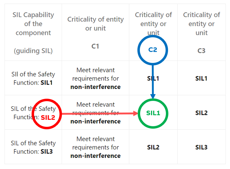
Based on the results of the Criticality Analysis and allocation, the required compliance for development, Verification & Validation and modification of the individual system or software unit with the requirements of IEC 61508 should be guided by the following Table 2.
Note: The following table shows how a lower criticality of the software unit may be used to reduce the required efforts (due to the SIL reduction of the “guiding SIL”).
| SIL Capability of the component (guiding SIL) | Criticality of entity or unit C1 | Criticality of entity or unit C2 | Criticality of entity or unit C3 |
|---|---|---|---|
| SIL of the Safety Function: SIL1 | Meet relevant requirements for non-interference | SIL1 | SIL1 |
| SIL of the Safety Function: SIL2 | Meet relevant requirements for non-interference | SIL1 | SIL2 |
| SIL of the Safety Function: SIL3 | Meet relevant requirements for non-interference | SIL2 | SIL3 |
Example:
If a component has a Capability of SIL2 and if a System Software Criticality Classification for a sub-unit results in a criticality of C2 for this sub-unit, then the SIL of this sub-unit can be reduced to SIL1. Thus, the sub-unit SIL is lower than the SIL of the component:
Remark: For software, that is considered to work as an Interference free function three options exist:
- No safety integrity requirements, if the interference freeness can be demonstrated, e.g., by the use of hardware memory protection (e.g. MMU);
- No safety integrity requirements, if the implementation languages for the pre-existing software product enforce encapsulation like Modula, ADA, and JAVA;
- The same safety integrity requirements as the safety function it interferes with, have to be used if option 1. or option 2. are not applicable.
Note: It is assumed that the timely interference of software functions is monitored by the logical and timely program flow monitoring as required by IEC 61508-2 ref [B3] .
Fundamental activities, such as Overall Safety Planning and Safety Requirements Specification, should meet the highest applicable SIL if they are used for the overall system. If they are used within the scope of a subsystem only, they may be executed as of the SIL of the related subsystem.
Development design and verification activities
Avoidance of systematic failures overview
A key element in safety development is the 'avoidance of systematic failures' during development. For that reason, the development has been grouped into development process lifecycle phases (see the Description of the Safety Lifecycle).
In the following sub-sections, there are:
- An overview of the development process lifecycle phases for the development of safety products (System, Hardware, Software and Libraries).
- A definition of the scope of the lifecycle phases (in brief PHASE or PHASES)
- An overview of the measures and techniques that are relevant for ensuring compliance to the safety-related standards during the individual PHASES depending on the safety integrity to be reached.
Avoidance of systematic failures, general requirements
Avoidance of systematic failures is at large extent based on good configuration management.
Follow-up and change control procedures shall be described to ensure that all change requests and recommendations for the various phases are properly addressed, especially recommendations arising from:
- Analysis, verification and validation activities.
- Functional safety assessment.
A change request database shall be used, at the latest starting with the formal test 'PHASE 5'. Further details are found in the CM-Process ref [C28] and written in the CM-plan.
Tests
The Test process ref [A5] describes the basic test categories that shall be used in development work. This model is used at several project levels. The details shall be described in an Overall Test Plan, section “Test Strategy”. Test process model ref [A5] defines the tests to be performed.
Definition of development PHASES
Development lifecycle and development PHASES overview
Introduction:
The following figure provides an overview of nine lifecycle phases from collecting requirements until the release of the product version. PHASE 10 (“Maintenance”) is not visible in this overview. Maintenance changes do follow after the product release and may require to re-run of a subset of the nine lifecycle phases depending on the scope of the change.
The phases can be arranged like the letter 'V'. This 'V-Model' is valid independent of the applied development model (e.g. "waterfall" or "agile"). For any function or product released, all relevant PHASES must be completed. Figure showing the V-Model for design, implementation and V&V activities:
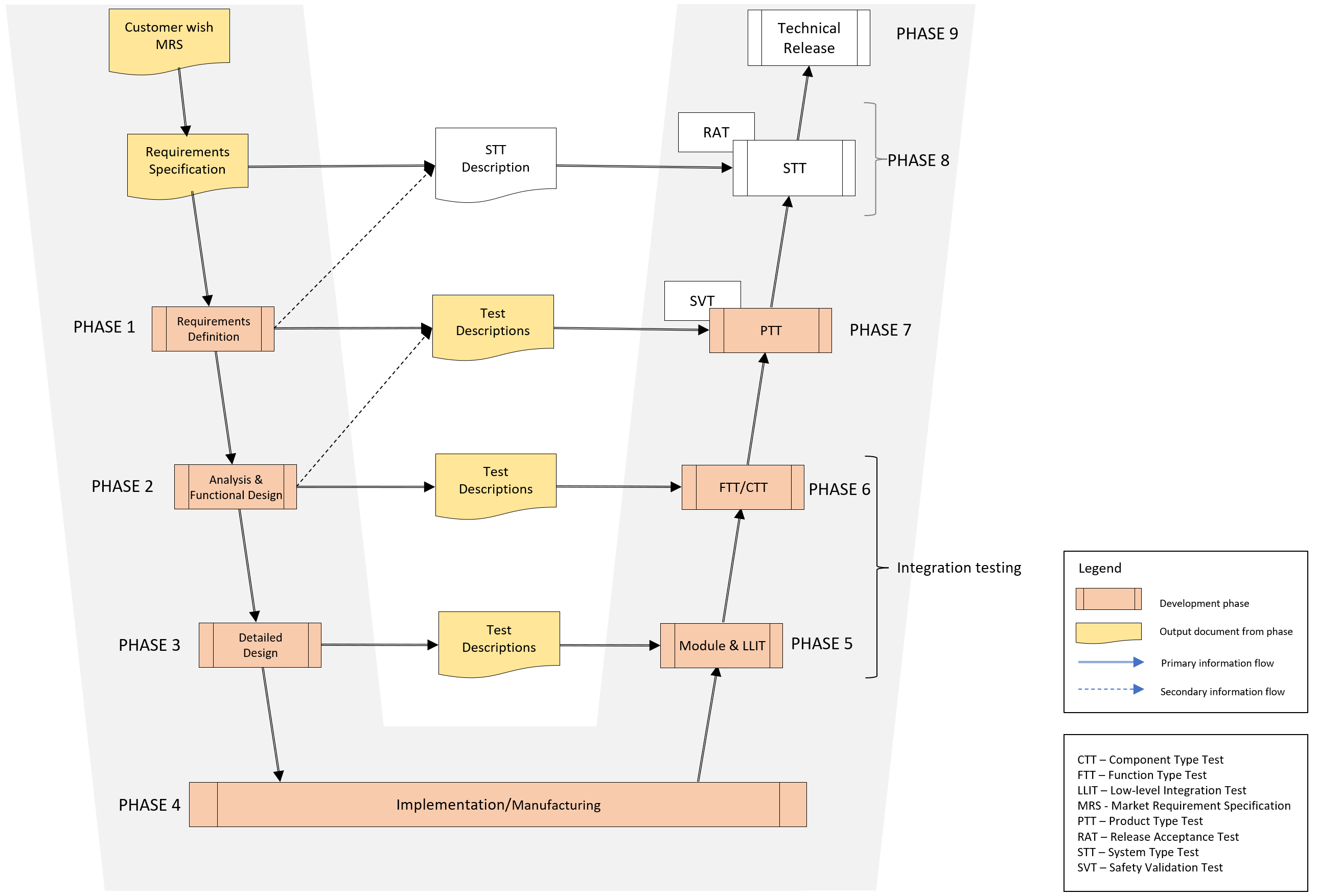
This figure shows the development of PHASEs in general, no matter if the development is dedicated to functional safety or not.
To get a more detailed overview of the functional safety-specific documents/artifacts click on the button below.
The yellow marked documents are functional safety-specific add-ons to the R&D QMS!
| Functional Safety Add On |
|---|
 |
After this introduction, there are:
- at first 10 sub-sections with general descriptions explaining the scope of PHASE 1 to 10.
- followed by the sub-section Avoidance of systematic failures PHASE 1 until PHASE 7 specific requirements describing the detailed measures for standard-compliant development during PHASES 1 until 7. Those measures are either directly taken from the standard(s) or have already been refined by ABB to fulfill the goal of avoiding systematic failures.
PHASE 1 Requirements definition scope
PHASE 1 (“Requirements Definition”) is concentrated on planning, analyzing and refining the market (user) requirements and on transferring those market requirements into product and safety requirements.
This phase defines the initial steps of a development project according to the Gate model. Each project shall be able to provide a list of documents used in the project. For planning purposes, this list can be created during the project in the form of a document control plan. As a source for types of documents see the RACI chart [A19]. All Baselines produced in the project shall be planned in a Baseline Plan.
Before the end of PHASE 1 the project baseline and architecture baseline shall be documented, see the [A45] baseline plan (template) for the specific project.
→ For mandatory measures on how to avoid systematic failures in PHASE 1, see Avoidance of systematic failures PHASE 1 until PHASE 7 specific requirements
PHASE 2 Analysis and functional design scope
PHASE 2 is concentrated on analyzing requirements and defining high-level packages for the product, as well as planning test activities and initializing user documentation.
This phase is carried out on the following two levels:
-
Level 1 - Architecture
- Output documents: Safety System Architecture and System Software Architecture
- Intention:
Analyze the safety and product requirements to describe the required hardware architecture and the main user characteristics of the complete product.
Expected output from both documents:
- A description of the main design criteria,
- high-level diagnostic functions including fault reactions,
- environmental and operating conditions
- applicable redundancy aspects of the system etc.
-
Level 2 - High-Level Design
- Output documents: Description of Functions
- Intention: The intention is to break down the identified development packages into functions of feasible size and complexity. The requirements are analyzed to describe the functions and facilities, including the interfaces that the product or component will provide, in such a way that the requirements are satisfied. The dynamic behavior should be the main focus and should be realized with e.g. sequence diagrams and state transition diagrams.
Action item: Before the end of PHASE 2 the functional baseline shall be documented, see Baseline plan (template) [A45] for the specific project.
→ For mandatory measures on how to avoid systematic failures in PHASE 2, see Avoidance of systematic failures PHASE 1 until PHASE 7 specific requirements.
PHASE 3 Detailed design scope
The designs for complex products that contain multiple components are performed in this phase. The intention is to split the product into separate components. This phase focuses on the components and modules described in the architecture and the detailed design of the interfaces between the components and modules. Analysis and Design Level:
-
Architecture (SW Architecture Design) By analyzing the input requirements and the proposed product (safety) architecture, the high-level software packages and their interfaces are identified and described.
-
Detailed Design (Design Descriptions) The intention is to analyze the described functionality and break down the functions into realizable design items. The detailed design shall include specifications of the necessary operations (methods) and attributes. In addition to static characteristics, detailed dynamic aspects should be described with state transition diagrams and sequence diagrams.
As a result of claiming a V-model, Test Descriptions shall be available from the previous phase together with other essential information. It is acceptable that these Test Descriptions are in draft status. As an example, when working on PHASE 3 activities Test Descriptions (acceptable in draft status) should be available from PHASE 2, and so on.
Design the module / single-module component by refining and "formalizing" the actual model as stated in the top-level design. Software shall be structured into suitable source code files and other implementation units, in such a manner that the requirements easily can be traced back and verified.
Hardware shall be designed with a focus on structuring the design into groups of functional units, e.g. power supply, diagnostics, field signal adaptation, etc.
Action item: Before the end of PHASE 3 the design baseline shall be documented, see baseline plan (template) [A45] for the specific project.
→ For mandatory measures on how to avoid systematic failures in PHASE 3, see Avoidance of systematic failures PHASE 1 until PHASE 7 specific requirements.
PHASE 4 Implementation and manufacturing scope
Realizing the intended design into source code and hardware prototypes.
→ For mandatory measures on how to avoid systematic failures in PHASE 4, see Avoidance of systematic failures PHASE 1 until PHASE 7 specific requirements.
PHASE 5 Scope of module / design and low-level integration test
In PHASE 5 the design of the component is tested to verify that the input design description is fulfilled. The test concentrates on the internal functions of the design and also on the functions interfacing with other components. In addition, the integration of software modules into components is tested. The relevant parts of the test description Baseline shall be documented, see Baseline plan (template) [A45] for the specific project.
→ For mandatory measures on how to avoid systematic failures in PHASE 5 see Avoidance of systematic failures PHASE 1 until PHASE 7 specific requirements.
PHASE 6 Function and component type test scope
In PHASE 6, the software is integrated with the hardware incrementally, i.e. both low-level tests with small hardware configurations and higher-level tests with larger hardware configurations are carried out. The functionality of the components is tested to verify that the input description of the function (Description of Function) is fulfilled. The tests concentrate on the correctness and consistency with respect to the functional requirements. Functional tests, fault-insertion, as well as performance tests are performed.
Action item: The relevant parts of the test description baseline shall be documented, see Baseline plan (template) [A45] for the specific project.
→ For mandatory measures on how to avoid systematic failures in PHASE 6, see Avoidance of systematic failures PHASE 1 until PHASE 7 specific requirements.
PHASE 7 Validation PTT and SVT scope
PHASE 7 validates the system against the requirements in the Safety Requirement Specification and the Product Requirement Specification (PRS). Concentrate on the correctness and consistency with respect to the functional requirements.
Guidelines and instructions for handling necessary corrections, as shown in the diagram above, are specified in the Quality Management System under the CM process “Configuration Change Control”. This includes the involvement of the CCB (Change Control Board) in the decision-making process.
Action item: The relevant parts of the test description baseline shall be documented, see Baseline plan (template) [A45] for the specific project.
→ For mandatory measures on how to avoid systematic failures in PHASE 7, see Avoidance of systematic failures PHASE 1 until PHASE 7 specific requirements.
PHASE 8 System type test
PHASE 8 validates product and component functions with respect to the requirements on a product level. The main focus of this test is to show compatibility between different versions of products and other ABB products. Another target of the System Test is to show that the system can work within the Network environments under normal and stress conditions.
The safety standard IEC 61508 ref [B1] gives no additional requirements to this stage of testing.
PHASE 9 Technical release
PHASE 9 releases the product. The main focus of this phase is to follow up that all the documents are completed, archive the product and documentation, and collect experience from the project, see Configuration Audits ref [A45] (functional and physical) and Release Preparations ref [A27].
PHASE 10 Maintenance
PHASE 10 handles the product after release and prior to the next release. The main focus of this phase is on the handling of unexpected behavior as reported from the field, field communication and fixes, that are small enough not to lead to a new, full version of the product. Modifications have to follow the change process as described in configuration change control in TFS ref [A23], [A53] and Application Lifecycle Management with TFS ref [A25].
If there are product issues reported after product release then there are resolution processes in place that have to be followed, depending on the potential impact of the reported issue:
- In case of requested modifications (e.g. reported bugs, customer requests, …) the change control board (CCB) coordinates necessary action. An impact analysis is then the first step prior to any change. Based on that impact analysis there is a decision on which parts of the "V-model" have to be followed with respect to the targeted change. The followed-up parts must then adhere to the matching parts of this document.
- In case of product-related issues affecting products already in operation the instruction on the "Field communication overview" has to be followed in order to achieve rapid reaction towards the end users (see Ref [A49]). Possible actions/reactions are “Stop order”, “products recall”, and “Field communication”.
- Writing and publishing of field communications are described in [C30].
- For certified correction of critical errors (not necessarily safety critical correction) there is a dedicated guideline to be followed [A50].
- The realization of a roll-up has to follow a dedicated guideline [C29]
- For the implementation of change requests for hardware units, a corresponding checklist has to be filled in [A54].
Avoidance of systematic failures PHASE 1 until PHASE 7 specific requirements
How to use this chapter (“Avoidance of systematic failures PHASE 1 until PHASE 7”):
| Non SIL Recommended SIL1 | Non SIL Libraries PA - Functions | SIL1 Required SIL1 | SIL2 Required SIL2 | SIL3 Required SIL3 | SIL Libraries IEC 61508 IEC611 |
|---|---|---|---|---|---|
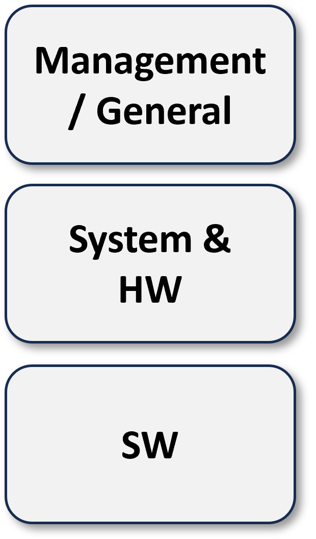 | 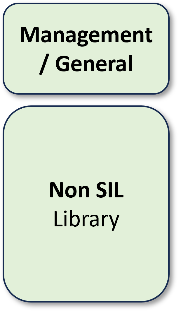 | 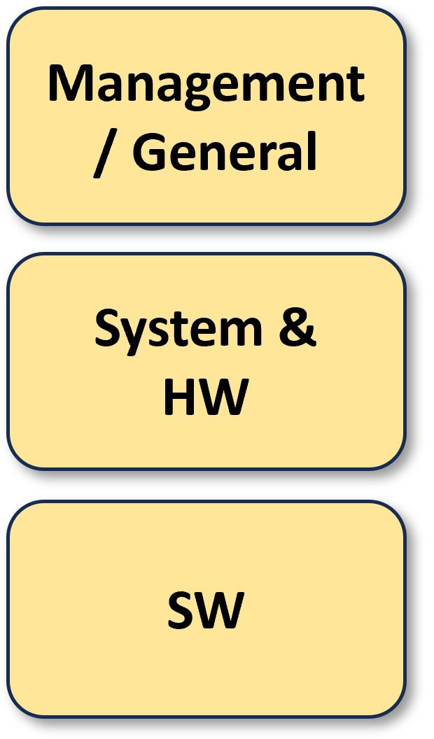 | 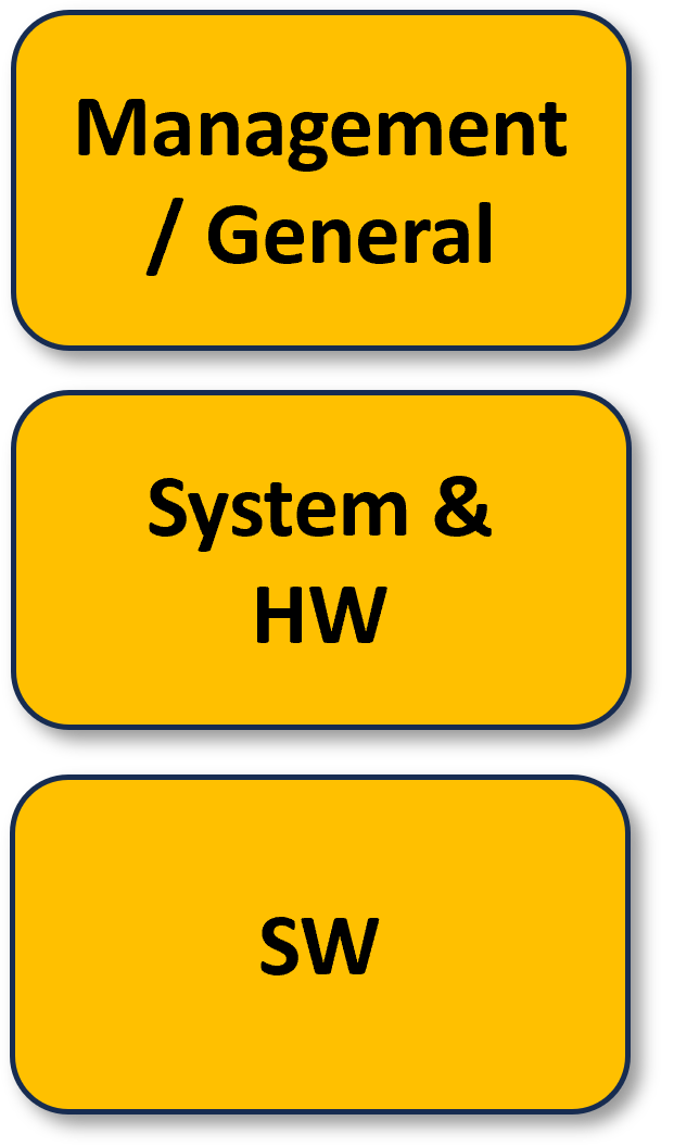 | 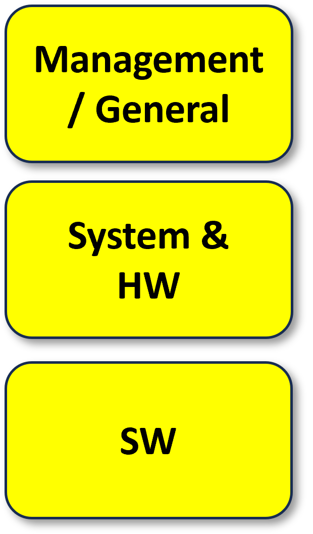 | 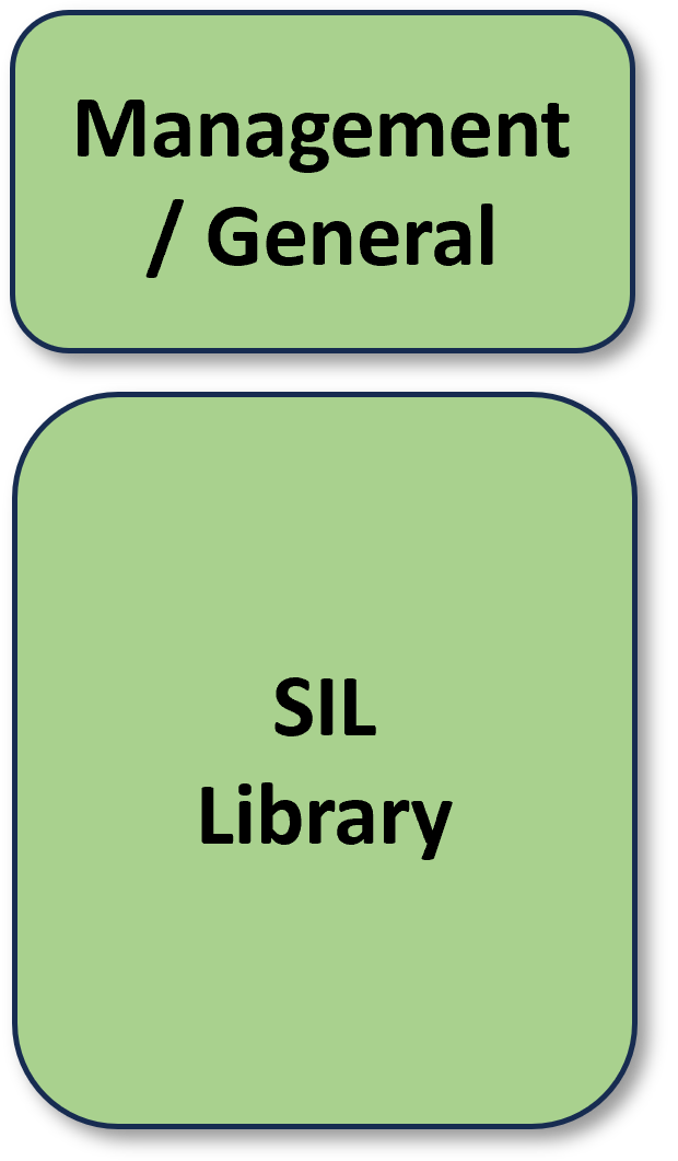 |
- Select the Safety Integrity Level intended for the functionality under change from the table (by clicking on the image).
- Follow the requirements as defined by the first section “Management/General”.
- Go to the section related to the kind of development (System, HW, SW, Library)
- Follow the requirements as defined for PHASEs 1, 2, …, 7.
- For requirements related to PHASEs 8, 9, and 10, see PHASE 8, 9, 10 in the description of the scope of the PHASEs.
Note:
Measures or Techniques in the following chapters are further described in detail in the following Guidelines:
[A6] 3BSE039242 ABB approach to IEC 61508 2nd Ed Design
[A7] 3BSE039245 ABB approach to IEC 61508 2nd Ed Test
The important measures and techniques can then be found in the following tabs.
If further information is needed the following flow can be used:
- Highlight the item in question (taken from the tab related to the corresponding development)
- Copy the item (→ Ctrl C)
- Go to the corresponding “ABB approach to the IEC… guideline (🡪 [A6] or [A7])
- Search for the item (→ Ctrl F to open the "find" function, Ctrl V to enter the item and a Return start the search in Word)
Verification and validation activities
Strategy for validation of requirements
The strategy for validation of all requirements, including the safety requirements, must be stated in a Test Plan.
Final conclusion of test
The final conclusion of test includes the test levels PTT and SVT. Included in PTT are both PTT SW and PTT HW (environmental tests and FIT). The test summary report (made in the Detailed Test Plan) shall include:
- Reference to the test plan
- Reference to the plan of HW and SW versions to be used in the test to have a good mixture of all supported versions.
- Reference to the specification for the overall requirements being used (PRS).
- Reference to the specification for the safety requirements being used (Safety RS).
- Reference to the test records.
- The SW and HW versions that are used under test (only safety modules and SW).
- Summary of the conclusion of test.
In the final conclusion of test:
- Provide an overall assessment of the HW / SW as demonstrated by the test results in the test records;
- Identify any remaining deficiencies, limitations, or constraints that were detected by the testing performed. Describe their impact on the system safety performance, including identification of requirements not met; and a recommended solution/approach for correcting it.
- Provide an assessment of how the test environment may be different from the operational environment and the effect of this difference on the test results.
The following information shall be available, but a reference is sufficient:
- The test environment, tools and equipment used, along with calibration data.
- The test procedures and performance criteria are to be applied to validate the specified electromagnetic immunity limits.
- The Justification Reports, generated from the Requirements tool have to be ready at the final conclusion of test.
See [A22] Review Process Guideline for a description of document handling.
Reviews
Document reviews
The scope of document reviews (the types of documents to be reviewed) is specified in the RACI chart ref [A19]. All document types in the RACI Chart shall be formally reviewed and approved using the document management system.
For details of the review routines and work processes follow the guidelines:
- [A22] Review Process Guideline (for documents with exception of user documentation)
- [A52] User Documentation Review Guideline (for user documentation)
The Safety Manual is a specific user documentation and shall be reviewed by the Independent Safety Assessor.
Code reviews
- All new or changed code shall be reviewed.
- i.e. all code checked into formal branches must be reviewed and have a code review comment.
- All test code shall be reviewed.
Review guidelines to be followed are:
- Review guideline for review of AutoSVT Code. See [A55]
- Review the process guideline for code reviews and description of document handling. See [A22]
- Code reviews need to be done within the collaboration software tool (Azure DevOps), i.e. the tool requires for each change of code an approval by two persons.
- Review of 'Design/Module and low-level Integration tests' with included test Description. See [A46].
- [A39] is a guideline that shall be used for the code review checklist, which can be found in the document "Checklist for Reviews" ref [A8].
Gate meetings
The gate model is used for all projects as a business decision model.
Gate meetings support verifying the outcome of each PHASE through Gate checklist verification for completeness and ready state.
- Add a ref to the “Milestone Tracker”
- RU-checklist for smaller projects
Standards, procedures and tools
Standards and procedures
Development work process model
Work processes for safety projects are based on IEC 61508 model ref [B1] and refined in this handbook. Iterations and parallel work have been allowed for in this model.
Tailored work processes
All tailoring of the standard work processes and quality elements (guidelines/instructions/templates/checklists) is possible.
The project SE and the QCM are responsible for any tailoring of the standard work processes. Any tailoring shall be documented in a Quality Plan. Compliance to the safety levels will be audited by the external, independent Safety Assessor.
Important decisions
All important decisions shall be documented and archived.
Tool selection and qualification
A CM Plan must exist and include a list of valid tools for a project.
If a tool is intended to be used in the context of the development of functional safety products, then an evaluation of the tool's criticality and a justification of the tool is required. This justification needs to be done in a Tool Selection Report ref [A20].
Traceability
IEC 61508 requires forward and backward traceability from requirements via DoF, and DD to implementation (code or HW circuitry) and to the related test descriptions.
- The general approach to the implementation of traceability in the main areas is described below.
- For the details on traceability see the document ABB Approach to Traceability ref [A37].
Traceability for software
- Traceability in Software is ensured via the Configuration Management (CM).
- The rules for check-ins are described in ref [A31]
- For source code, a reference to a Configuration Change case from the code check-in is required. See ref [A23], [A53].
- Further details and any deviation must be described in a CM Plan.
- Aspects to be considered for tracing include documents, tools, HW, SW, test, verification results, and validation results.
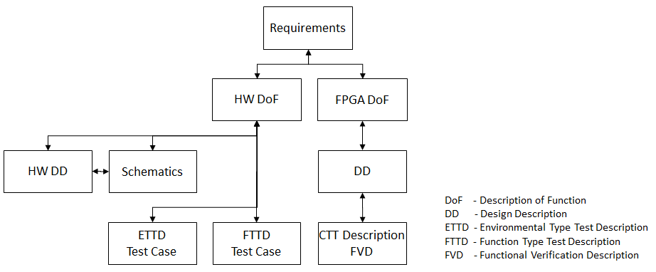
Traceability for hardware
Since HW Descriptions of Functions are created in MS Office documents, the traceability needs to be done manually on the chapter level. The following figure shows the HW Traceability:
Traceability of deviation handling
The CM Plan shall define the defect tracking system to be used.
The deviation handling shall provide each entity with the following information:
- The status of the deviation handling / the affected software, hardware, documentation
- Who is currently responsible
- Severity
- If the deviation is corrected: what changes have been made, which file versions contain the changes, and in which product/component version are/will the changes be released
- Effect on Safety and Security
For more information, see Configuration change control in TFS ref [A23], [A53].
Deviation handling
Details about deviation handling are found in the CM-Process ref [C26], the projects CM-plan and configuration change control in TFS ref [A23], [A53].