Guideline for HAZOP
The objective of this guideline is to describe the procedure of how to perform HAZOP analyses for Electrical/Electronic/Programmable (E/E/PE) safety-related systems, explain the reasons for performing a HAZOP, give an overview of the process, and explain the terminology and concept. The HAZOP is a recommended technique in IEC 61508.
Introduction
A hazard and operability study (HAZOP) is a structured and systematic analyzing technique for examination of a defined system in order of identifying potential hazards and operability problems in the system. The HAZOP is categorized as a qualitative hazard analysis method.
The analysis is carried out by breaking down the system’s operations into smaller, clearly defined segments generally called nodes. In ABB, nodes are denoted as entities. The entities are then individually examined to determine if a deviation from its intended function may lead to a hazard and what measures exist to prevent that from happening. Similar entities can be grouped together to facilitate an assessment.
The examination is typically carried out by a multidisciplinary team with different viewpoints during a set of meetings, see Roles of the HAZOP team members for a description of the different roles that participate. Identification of deviations from intended function is facilitated by using guidewords on each entity and then describing possible causes, consequences of the deviations and required actions.
The HAZOP can suitably be conducted several times during development in order to gradually return the information to the designers and thereby obtain a safer system. Since the HAZOP analysis is a relatively simple analysis to conduct, it can be performed early in design work.
Methodology
The HAZOP is divided into three principal, sequential stages, illustrated below:

Plan the analysis, define scope and objectives
The first stage of the HAZOP includes:
- selection of the analysis team
- definition of scope and objectives
The first stage is initiated by selecting the team members (typically a team of 5 -7 persons with dedicated roles according to Roles of the HAZOP team members). The HAZOP team shall consist of multi-disciplinary team members who possess broad and current knowledge of the functionality intended for the analysis.
The team then defines the objectives and scope of the analysis, i.e. the (sub-) entities the analysis shall include. This includes defining boundaries and interfaces as well as identifying assumptions that the analysis will be performed under. The input data, support data and information are collected, and the meeting(s) are planned.
Guidewords
The team is also responsible for evaluating the guidewords that will best suit the scope and problem statement for their analysis. The generic guidewords used by ABB are described in the table below. For specific guideword interpretation for real-time operating systems, object interactions and message-sequence diagrams, dataflow diagrams, state transition diagrams and entity relationship diagrams, see SILcap User Manual .
| Guideword | Standard interpretation | Example interpretation |
|---|---|---|
| No | No part of the intention is achieved. | No signal passed. |
| More | A quantitative increase. | More signals are passed than intended. Regarding a value it means that the value is too high. |
| Less | A quantitative decrease. | Not used here because this is already covered by ’part of’. Regarding a value it means that the value is too low. |
| As well as | All design intent achieved but with additional results. | Not used here because this is already covered by ’more’. |
| Part of | Only some of the intention is achieved. | The signal information is incomplete. |
| Reverse | The logical opposite of the intention is achieved. | Normally not relevant. |
| Other than | A result other than the original intention is achieved. | The signal information is complete and syntactically correct but functionally/semantically incorrect. |
| Early | Something happens earlier than expected relative to clock time | The signal arrives too early with reference to clock time. |
| Before | Something happens before it is expected, relating to order or sequence. | The signal arrives earlier than intended within a defined sequence. |
| Late | Something happens later than expected relative to clock time. | The signals arrive too late with reference to clock time. |
| After | Something happens after it is expected, relating to order or sequence. | The signals arrive later than intended within a defined sequence. |
Perform analysis
At the analysis meeting, each entity is examined systematically by using the pre-defined guidewords. The objective is to identify what deviations from the intended design could occur in the relevant attributes of the entities, and then to determine their possible causes and consequences. Impacts of interconnections between different entities are also examined.
The procedure for identifying deviations from the intended design for one entity or interconnection is:
- Select an entity. Describe its intended function of process
- Interpret the guidewords and decide which are applicable for the entity
- Apply first guideword
- Determine deviation
- Identify and state possible cause(-s) and consequence(-s) for the system as a whole
- State any safety measures which aid the detection or indication of hazards
- Repeat 4-6 until no more deviations can be determined
- Apply next guideword
- Repeat 4-6 until no more deviations can be determined
- Repeat 8-9 until no more guidewords are left
- Document the results and unresolved issues (could be done by using a HAZOP tool, see HAZOP tools). The unresolved issues shall be documented as items in the appropriate defect tracking system (such as ADO or similar).
Follow up
If hazards have been identified, they may require that new safety measures need to be implemented to eliminate the hazards or reduce their effects on the system. A specific recommendation on additional safety measures will be made and documented in the appropriate defect tracking system (such as ADO or similar).
Follow-up of documented uncertainties and open questions from the meetings must be performed.
All documentation is agreed by the team and signed off by the analysis leader. The analysis and its results are then documented in a HAZOP report. The HAZOP analysis report is then formally approved by the Functional Safety Manager.
Roles Of The HAZOP Team Members
A well-conducted HAZOP analysis meeting is a team effort, with each team member having a dedicated defined role. The recommended team roles are described in the following sub chapters.
Facilitator
Qualification:
- Independent of the project/system, but with knowledge of the design representations and technical field of the system
- Experienced in leading HAZOP analysis meetings
Task(s):
- Provide the planning (Recommendation is to keep the sessions a maximum of 3-4 hours at a time) and control necessary for a successful analysis
- Responsible for progressing through the series of entities, see Perform analysis
- Summarize the results of the discussion and draw conclusions from them
Recorder
Qualification:
- Be competent at recording, in concise prose, the results of a diverse discussion
Task(s):
- Assist the facilitator to provide the administration of the analysis
Note that it is strongly recommended that the facilitator and the recorder should be two different persons.
Designer
Qualification:
- Detailed understanding of the design and its representations to be studied
- Be capable of explaining how defined problems could be caused and how the system would behave in their presence
Task(s):
- Responsible for explaining the design intent
User or intended user of the function being analyzed
Qualification:
- Be able to explain what the operational consequences of a defined deviation could be and the extent to which they may be hazardous
Task(s):
- Advise on operational matters and on the environment within which the system operates or is intended to operate
Expert
Qualification:
- A competent explorer of cause and effect within the system
Task(s):
- Provide the knowledge and experience necessary for identifying and assessing hazards caused by the errors identified.
ABB Scope/Approach To HAZOPs
The HAZOP shall be performed for new functionality being introduced or for changed functionality where it is assessed as necessary to perform such an analysis.
There are two types of HAZOP performed:
- Pre-HAZOP
- HAZOP
Pre-HAZOP
A Pre-HAZOP is a formally structured analysis of a system or system part using the same methodology as a HAZOP but based on less detailed information.
The Pre-HAZOP is performed early during a development project, preferably during Phase 1 (Requirements and Definitions) or Phase 2 (Analysis and Functional Design) defined in Safety Handbook.
The input documents for the Pre-HAZOP could be the Product Requirement Specification (PRS), the Safety Requirement Specification (SafetyRS), the Implementation Proposal (IP), the System Software Architecture, the Safety System Architecture or other types of early project descriptions. The analysis, at this stage, is performed in order of identifying hazards in the proposed system architecture for both new functionality and for changed functionality, their possible causes and consequences and recommending measures in order of minimizing the probability of the hazards occurring. The Pre-HAZOP is also used as an aiding tool in the planning of the forthcoming project activities.
The focus for the pre-HAZOP is on identifying the potential hazards and operability problems in order of mitigating those before further design development occurs. It is not used for assessing the initial criticality of new functionality. The designation of verifying the initial SIL and criticality is part of the HAZOP, see below. Criticality for 800xA System is assessed according to 3BNP004305D0512 System and Software Criticality Analysis and 3BSE072135 System FMEA Select I/O.
HAZOP
The HAZOP is performed during Phase 2 (Analysis and Functional Design) and/or during Phase 3 (Detailed Design) defined in Safety Handbook.
The input documents for the HAZOP could be the Description of Functions (DoF) and/or the Design Description (DD). The analysis, at this stage, is performed in order of identifying hazards in the proposed design, their possible causes and consequences and recommends measures in order of minimizing the probability of the hazards occurring.
The HAZOP verifies the specified criticality which is the basis for the SIL reductions made on different system parts. The HAZOP is not used for assessing the initial criticality of new functionality.
HAZOP Tools
A HAZOP is not bound to specific tools and can be conducted and documented based on general tools such as Excel or Word. For ease of use, ABB is applying several tools that can be used for conducting the HAZOP such as SILCap and SafetyInsight.
SILCap was developed by the external company Exida. The user manual for this tool is stored within the tool itself. SafetyInsight was developed by ABB PAEN. The user manual have document ID 3BNP102815-200 (-200 is the denomination of the version of the tool). To use any of these tools, please contact the Functional Safety Team.
Deviations in terms
The differences in terms between the tools and the general denominations are listed in the table below:
| General term | SILCap | SafetyInsight |
|---|---|---|
| Cause | Cause | N/A |
| Deviation | Consequence | Failure Mode |
| Guideword | Keyword | Guideword |
| Interpretation of guidewords | Interpretation | Context |
| N/A | N/A | Risk types: Intended by the tool to separate different kinds of risks. "Safety" used in generalp. |
| N/A | N/A | Severity: Used to assess how severe a consequence is on a measureable scale |
| Node/Entity | Unit | Node |
| Safety measure | Safety measure | Prevention Safeguards and Mitigation Safeguards |
| Unresolved issues | Required activity | Action and Observation |
Tailoring
SILCap
Criticality assessment
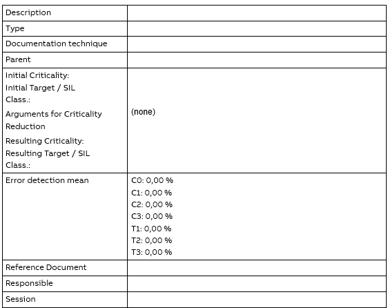
In the tool, there are fields for the initial/resulting criticality (or, alternatively, the tool class) and the initial/resulting SIL/target classification of the units. This is a functionality not used in the tool. In the resulting print out report this will appear as a yellow marked “C” in the HAZOP result table, see below:

Since the criticality and SIL functionality are not used in the tool, the safety measures are not assigned error detection mean values. This will also affect the table for the “Unit Classification”, where the error detection mean value will be zero, since this value represents the algebraic mean value of all defined error detection, see below:
SafetyInsight
Please, see annex A in 7PAA010740_en Safety Tool Selection for ABB SafetyInsight.
Definitions/Terminology
| Term | Expansion/Description |
|---|---|
| Attribute | Property of an entity, either physical or logical. |
| Component | Discrete structure, such as an assembly, within the total system, considered at a particular level of analysis. This is meant in the broadest sense and includes hardware, software, mechanical, electrical and electronic elements, either physical or logical. |
| Design intent | Interpretation of the required or specified behavior or range of behavior, of an aspect of the design (usually an attribute). |
| Design representation | Descriptive model of the design of a system or part of a system presented according to a convention (for example, block diagrams, data flow diagrams, or state transition diagrams). Here, ‘design’ is not limited to an abstract representation of local design, but may include implementation details, physical details, environmental details and operating instructions; it is a description of the system under analysis. |
| Deviation | Discrepancy of the value of an attribute of the system from its design intent. |
| E/E/PE | Electrical/Electronic/Programmable Electronic safety-related system |
| Entity | An entity is a part of the system that has certain attributes. There are two levels of entities of interest for a HAZOP analysis. Entities on system level: - System components - Interconnections between system components Entities on component level: - The component itself - Interconnections between components In a HAZOP, the attributes of the entities are examined. For the components and interconnections which are displayed on a design representation, ‘entity’ is a necessary intermediary in the identification of attributes. As an example, if a component is a E/E/PE, one of its entities is its processing unit which possesses the attribute of ‘throughput’. An interconnection between components may carry entities such as ‘data’ and ‘control data’ both of which may possess the attributes ‘value’ and ‘bit rate’. See also node. |
| Event | Significant happening that may originate in the system or its operating environment. |
| Failure | Inability of a system or component to fulfill its operational requirements. Failures may be systematic or due to physical change. |
| Function | Aspect of the intended behavior of the system. |
| Guideword | Word or phrase which expresses and defines a specific type of deviation from design intent. |
| Hazard | Physical situation, often following from some initiating event, that can lead to an accident. |
| Hazard Analysis Method | Analysis focusing on identifying the hazards which may expose risks to personnel or equipment. The qualitative hazard analysis, such as the HAZOP, focuses on identifying potential hazards and causes, often based on experience, whilst the quantitative analysis focuses on calculating the probability of the identified hazards and describing the risks in absolute values. The quantitative analyses demand rigorous and specific input data. |
| HAZOP | Hazard and Operability Study |
| HAZOP Analysis Meeting | Period during the HAZOP analysis process when the analysis team meets to carry out the examination of one or more design representations. The meeting is conducted according to formal rules. |
| Interconnection | Link between two components (at whatever level) within a system, which exists because of (and is defined by) an interaction between the components. This link may be logical or physical. |
| Node | The broken down, simpler segment of a process used in the analysis. The nodes shall be so specific that the HAZOP Analysis Meeting team can understand all possible causes and consequences for each deviation within that node. See also entity. |
| Operability | Capacity of a system to function. |
| Risk | Combination of the frequency, or probability, and the consequence of an accident. |
| System | Bounded physical entity that achieves in its environment a defined objective through interaction of its parts. |
| V&V | Verification and Validation. Validation answers the question: “Are we building the right product?” Verification answers the question: “Are we building the product rightly?” |
Example Of A HAZOP
In the following chapter an example of a how a HAZOP analysis can be carried out using the attribute “trip point” is described. Note that this is just an interpretation of the attribute and not a full analysis investigating all potential scenarios and hazards relating to that attribute. “Trip point” is considered to be a critical attribute of a E/E/PE safety-related system that shall lead to the opening of a valve in case a maximum value is reached.
| Guideword | Interpretation of guideword | Cause | Consequence | Safety measure |
|---|---|---|---|---|
| No | - No trip point available - No receipt of the sensor signal - No reaction of the valve | - Incorrect configuration - Incorrect program flow - Memory error - Incorrect program - Faulty or incorrect connected sensor - Faulty valve or incorrect control of the valve | No actuation of the safety function on demand | - Configuration control – functional test - Logical and temporal program flow control - Memory test - Program verification during operation - Installation procedure - System test before commissioning - Use of self checking sensors and valve control logic - Use of redundant sensors with comparison and valve control logic with read-back of the valve position |
| More | - Value of the trip point too high - Incorrect receipt of the sensor signal | - Incorrect configuration - Memory error - Faulty sensor | Actuation of the safety function happens too late | - Configuration control – functional test - Memory test - System test before commissioning - Use of self checking sensors - Use of redundant sensors with comparison |
| Less | - Value of the trip point too low - Incorrect receipt of the sensor signal | - Incorrect configuration - Memory error - Faulty sensor | Actuation of the safety function happens too early | - Configuration control – functional test - Memory test - System test before commissioning - Use of self checking sensors - Use of redundant sensors with comparison |
| Reverse | Incorrect behavior with regard to the trip point | - Incorrect program - Incorrect control of the valve | Actuation of the safety function as long as the trip point is not reached yet; no actuation of the safety function when the trip point is reached | - Program verification during operation - System test before commissioning - Use of self checking valve control logic - Use of redundant valve control logic with comparison |
| Early | The trip point is reached too early | - Incorrect configuration - Incorrect program flow - Memory error - Incorrect program - Faulty or incorrect connected sensor - Incorrect control of the valve | Premature actuation of the safety function | - Configuration control – functional test - Logical and temporal program flow control - Program verification during operation - Memory test - Installation procedure - System test before commissioning - Use of self checking sensors and valve control logic - Use of redundant sensors with comparison and valve control logic with read-back of the valve position |
| Before | Additional unintended trip point before the critical trip point | - Incorrect configuration - Incorrect program - Faulty or incorrect connected sensor - Incorrect control of the valve | Premature actuation of the safety function | - Configuration control – functional test - Program verification during operation - Installation procedure - System test before commissioning - Use of self checking sensors and valve control logic - Use of redundant sensors with comparison and valve control logic with read-back of the valve position |
| Late | The trip point is reached too late | - Incorrect configuration - Incorrect program flow - Memory error - Incorrect program - Faulty or incorrect connected sensor - Incorrect control of the valve | Delayed actuation of the safety function | - Configuration control – functional test - Logical and temporal program flow control - Program verification during operation - Memory test - Installation procedure - System test before commissioning - Use of self checking sensors and valve control logic - Use of redundant sensors with comparison and valve control logic with read-back of the valve position |
| After | - Trip point too high Re-start after actuation of the safety function | - Incorrect configuration - Incorrect program flow - Memory error - Incorrect program - Faulty or incorrect connected sensor - Incorrect control of the valve | - Delayed actuation of the safety function Uncontrolled system behavior | - Configuration control – functional test - Logical and temporal program flow control - Program verification during operation - Memory test - Installation procedure - System test before commissioning - Use of self checking sensors and valve control logic - Use of redundant sensors with comparison and valve control logic with read-back of the valve position |