Architecture Document Structure
This document provides a guideline for structuring architecture documentation in the PAPCP R&D environment.
Other guides have described how an architecture document shall be written and reviewed, in this document, we will describe how different documents shall be organized and linked to support navigation and understandability to different categories of users.
Intended for
Architects.
Architecture organization
It is important to remember how the architecture organization works in PAPCP to understand how architecture documentation should be structured since documentation should adapt to this.
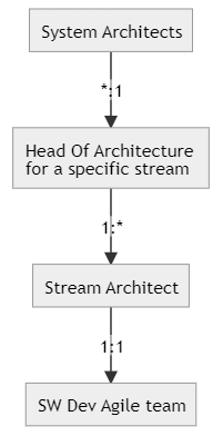
This diagram shows how architecture spans from the system architecture down to individual software module architecture and how different teams contribute to it. It becomes increasingly evident that good governance needs to be enforced to guarantee consistent documentation.
Tooling and techniques
Within PCP, it's recommended to write design documents in Markdown and publish the .md files on wiki pages (available wiki pages for different architecture levels are listed and linked to under References). Still, the scope of such documents isn't clear, neither the toolchain to create them.
It's highly recommended that we follow a consistent documentation flow, which could ideally span from a high-level architecture to lower details. Such a method would nicely map to our organization, too.
To support such a documentation strategy, we sponsor the use of C4 modeling, which conceptually layers the architecture documents starting from a high-level context down to the software modules' UML description.
NOTE: C4 doesn't describe how the architecture documents should be written; it is just a conceptual guide that gives directions and formalities for describing a software system with a progressive number of details.
The image below (from the C4 modeling website), with an analogy to Google Maps, shows how a high-level design document can be mapped to the world map, while a UML description of a code module can be mapped to pictures in Google Street View.
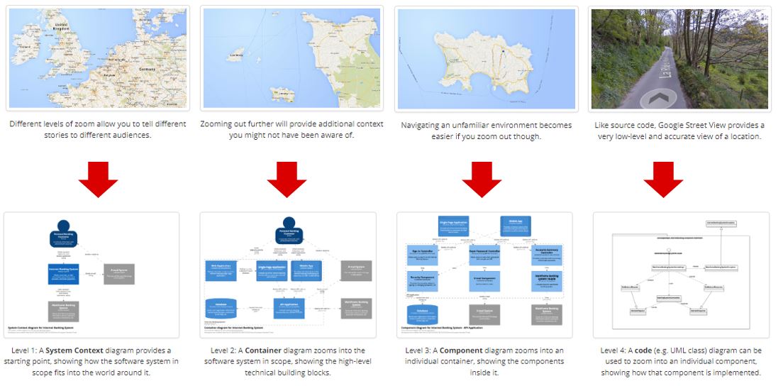
In the next paragraph, how this mapping would work in the PAPCP organization is explained.
C4 Modelling, although it comes with a specific formal representation of objects (the 4 Cs), doesn't rule over any specific tool to be used to create C4 diagrams. However, several tools can be used for the creation of the diagram. Some of them are "WYSIWYG" (what you see is what you get), like VISIO (with C4 stencils add-on), PowerPoint (with C4 template), or Draw.io (with C4 extension). Others are based on scripting.
The last suggestion is PlantUML with a C4 extension; see References for more details. It isn't a visual tool but allows you to easily create diagrams without drawing directly but just via a text-based interface. This can be convenient during reviews to annotate comments, which is harder to do on pictures. Moreover, PlantUML can be integrated into an integrated development environment (IDE) such as VSCode to simplify the editing.
NOTE: Different technologies can be combined to produce C4 diagrams. For example, PlantUML might not be easy to use for very complex diagrams since there are fewer chances to influence the drawing rendering, so other tools, such as draw.io, might be more useful. The overall result by combining the drawing in a single wiki will be successful since the formal representation is the same independently of the used tool.
Besides C4
Architecture documents can be very complex and may require a different kind of diagram to represent the software behavior. It is important to understand that C4 isn't replacing any of the best practices for documenting system interactions but is giving extra tools to describe an outside-in view of a complex system.
All the usual best practices used to describe dynamic behavior, such as sequence diagrams and static aspects, such as deployment diagrams, shall still be used in the proper C4 layers. In the code layer, for example, it is still a good practice to use UML to describe the details of the software.
Some topics, such as information modeling, may not easily map to any of the C4 layers, and in different cases, it may apply to more layers. A possible approach could be creating dedicated sections in the document describing the context, container, or component that owns those parts of the system information model.
C4 modeling and PCP architecture documentation mapping
Previous sections cover:
- What does the PCP architecture organization look like (and how does it map to development streams)?
- How is a logical flow of architecture documents created (and which tool should be used)?
In this section, these two things are combined to define which architects should work in which documentation area.
The following picture shows, on the left side, the different architecture teams (as described earlier) and the C4 layers.
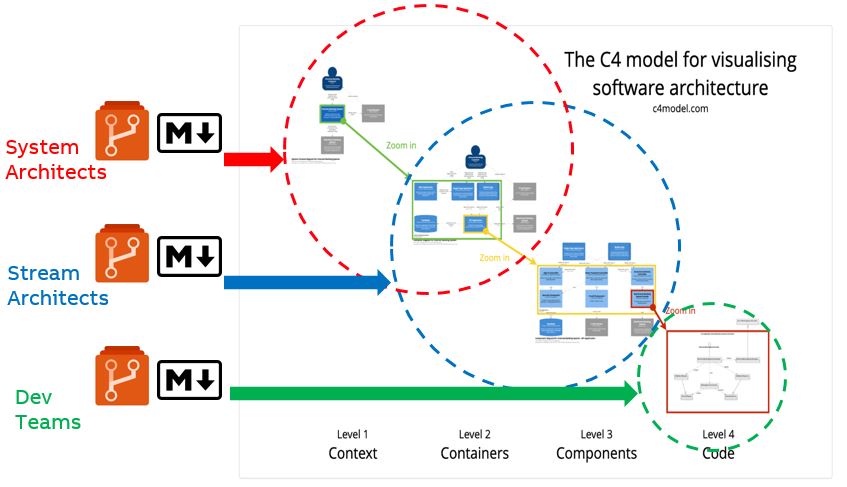
The picture shows the following responsibilities:
- System architects: Are mainly responsible for the context view. At this level, the system is described in an abstract way, including the cooperating external systems. But considering that system architects are even the "head of architecture" of a certain stream, they will have to support the definition in more detail of a certain system function they belong to. Therefore, they will also be responsible for the container view level.
- Stream architects: They work most of the time at the level of container view, where they explain how a certain subsystem will work and its internal details. They are also responsible for defining the component view details of the container they have worked with.
- Development teams: Are responsible for describing the details of the code modules they implement. Depending on the needs and processes behind them (e.g., UML or simply descriptive Markdown pages), the description can involve more or fewer formalities.
One crucial aspect to consider is that the wiki pages where the architecture documents will be stored will be different depending on the different layers (see links under References). Still, for the code level, the description shall stay with the repo of the code module it describes. This will help in packaging the description of the code module together with its code and version it in the same way.
C4 modeling mapped to our organization and wiki pages in ADO enables a reading flow for multiple users. We can read it from the top down (starting from the high-level context in system architecture and going down to the level of details we're interested in) or bottom-up (starting from a code module and going up to the context where it is supposed to be used). In this way, differently skilled people can read the documents the way they prefer or need.
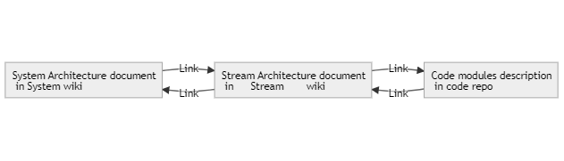
Example: Certificate management is a broad topic that starts from system architecture, where we describe how certificates are issued and distributed to different system parts (e.g., Runtime, Engineering) and how their life cycle is managed. This part of the description shall be stored in the system architecture wiki with context and container diagrams. The implementation details on certificate distribution and the components involved shall be described in the stream architecture wikis (mainly Operations and Engineering). At the same time, the code module description shall be consistent with the certificate management implementation. With proper hyperlinks in the Markdown pages, navigating through different areas of the wiki pages smoothly will be possible.
The following picture sketches what's described above in a single diagram, showing the connection across the different wiki pages, their grouping, roles, and responsibilities.
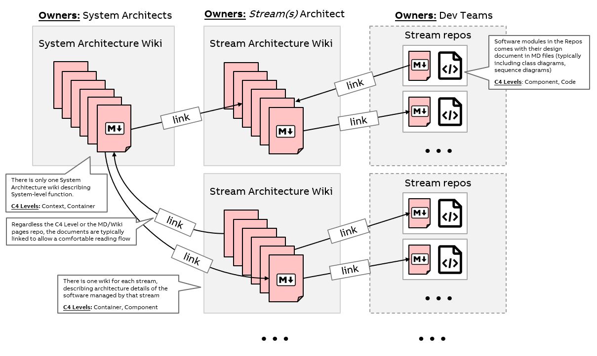
Considerations on C4, wiki and AV
The overall Automation Vision (AV) system is going to be described by the collection of all the wiki pages in the different repos at different C levels. However, the architecture documents shall be agnostic from the products that will incorporate the NextGen technology or from the different deployment options. Nevertheless, references to products and deployment are allowed for easy navigation to the proper documents, but no extensive description shall be part of the technical documents, they have to be kept intentionally abstract from the deployment and product branding.
Example: We shall avoid mentioning System 800xA or Symphony Plus, as well as panel or thin client deployment, in any of our architecture documents. Instead, specific architecture documents for the productization shall describe such deployments in detail.